Vibration Analysis of Thermal Control Unit
- January 23, 2026
- CAVU Aerospace UK
Vibration analysis is a critical component of mechanical qualification for spaceborne electronics. During launch and ascent, avionics hardware is subjected to intense broadband random vibration, sinusoidal loads, and shock events that can induce significant dynamic stresses and structural deformation. These effects are especially critical in regions hosting high-density components such as field-programmable gate arrays (FPGAs), where excessive board deflection can directly impact electrical performance, solder joint reliability, and long-term system robustness.
In the present analysis, particular attention was given to the FPGA region of the board, as this area represents both a mechanically sensitive zone and a functionally critical element of the system.
Simulation Conditions and Load Case Definition
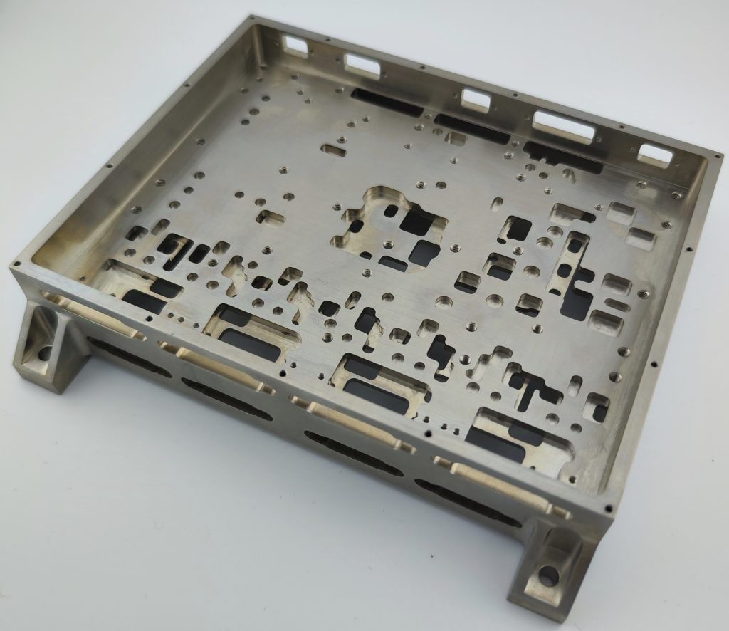
Prior to fabricating the boards, a preliminary analysis was conducted about method of fixing the TCU control & driver boards in enclosure box. The material properties for the PCB have been taken as those of FR4. TCU control board has 33 fix point including 8 points from 4 connectors distributed in surface of the board.
TCU driver boards has 26 fix points including 8 points from 4 connectors.
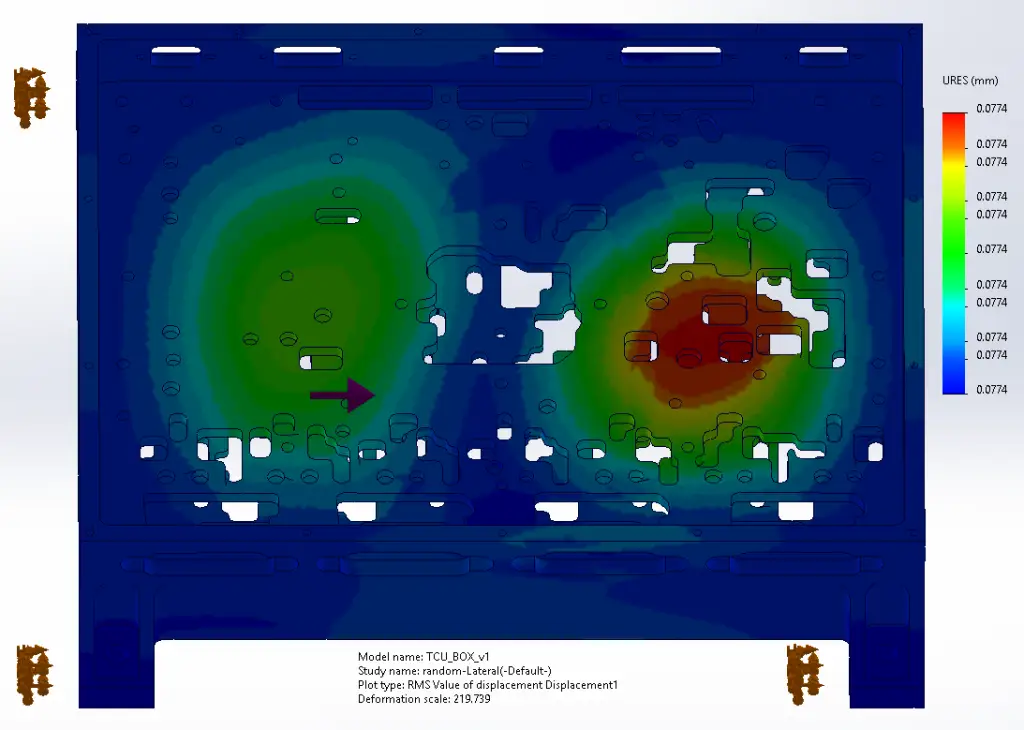
The vibration assessment was performed under a combined loading scenario representative of launch conditions. This included:
- Z-direction dynamic excitation consistent with block-level vibration testing profiles
- Boundary conditions corresponding to a free face on the FPGA side of the board
- Structural constraints applied at mounting interfaces to replicate realistic spacecraft integration
This configuration represents a conservative case, as the presence of a free face allows higher local deformation than would be expected in fully constrained operational mounting conditions.
Maximum Deformation Results
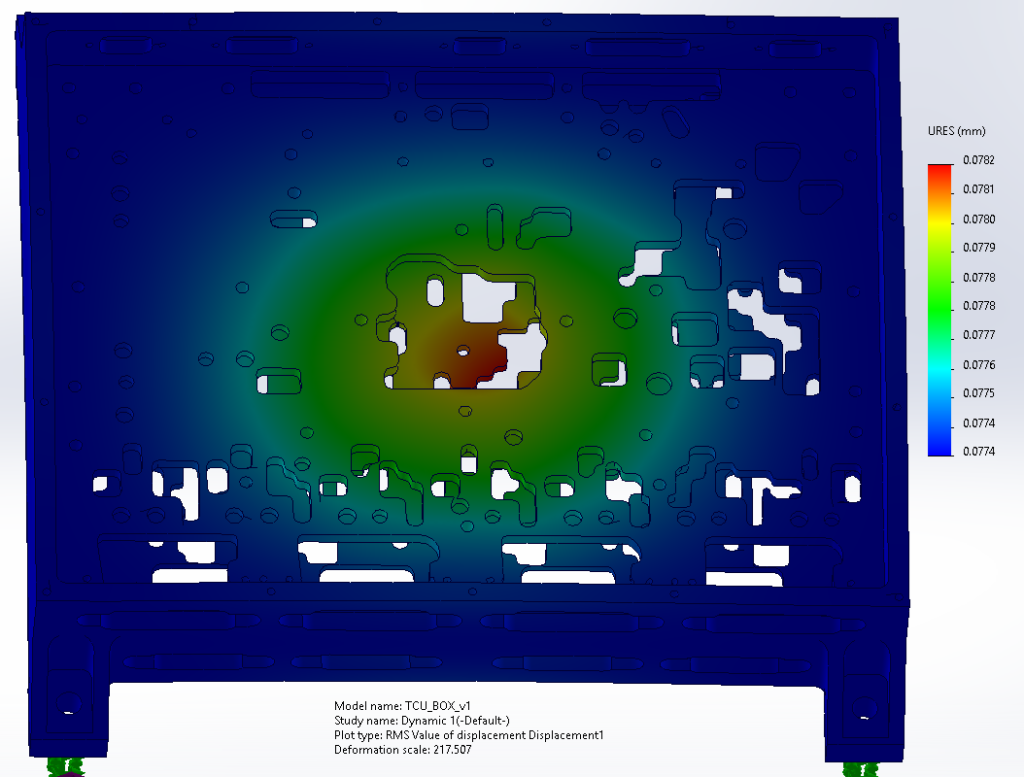
The finite element simulation indicates a maximum deformation of 0.0782 mm in the FPGA region under Z-direction vibration loading.
This displacement value is significant for several reasons:
- It remains well within typical allowable limits for high-reliability PCB assemblies.
- It ensures mechanical stability of the FPGA package and surrounding interconnects.
- It supports continued functional performance of the Timing and Control Unit (TCU) at simulation level.
The result demonstrates that the board layout, layer stack-up, material selection, and mechanical support strategy provide sufficient stiffness to control dynamic bending under severe vibration environments.
Importance of FPGA-Region Deflection Control
The FPGA is one of the most mechanically and thermally sensitive components on the board due to:
- High pin density and fine-pitch solder joints
- Large package footprint
- Elevated mass relative to passive components
- Central role in system timing, data handling, and control logic
Excessive deflection in this region can lead to:
- Solder joint fatigue or cracking
- Intermittent electrical connections
- Micro-fractures in the PCB substrate
- Degradation of signal integrity
- Long-term reliability issues under cyclic loading
For these reasons, minimizing displacement in the FPGA area is a primary structural design objective.
The observed deflection of 0.0782 mm, even under conservative free-face conditions, indicates a mechanically robust design margin for both qualification and operational phases.
Correlation to Hardware Integrity and Performance
From a functional standpoint, maintaining low deformation directly contributes to:
- Stable clock distribution and timing margins
- Consistent high-speed signal routing performance
- Reduced mechanical stress on ball grid array (BGA) solder joints
- Preservation of FPGA internal die integrity
At the system level, this supports reliable operation of the TCU and associated processing functions throughout launch and mission phases.
Design Implications and Engineering Validation
The vibration simulation results validate several key design choices:
- Adequate PCB thickness and layer construction
- Effective component placement strategy
- Appropriate stiffening through mechanical mounting points
- Controlled mass distribution around the FPGA zone
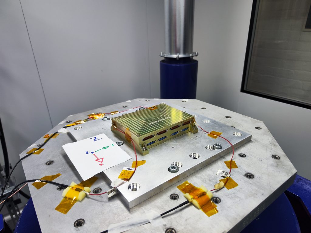
Furthermore, the block-level Z-axis vibration case provides a strong basis for subsequent:
- Qualification vibration testing
- Acceptance testing
- Model correlation between simulation and physical measurement
The vibration analysis demonstrates that the maximum deflection in the FPGA region is limited to 0.0782 mm under Z-direction vibration with a free face boundary condition. This low level of deformation confirms that the structural design is capable of maintaining hardware integrity and supporting reliable TCU performance under launch-induced dynamic loads.
Controlling deformation in critical electronic regions such as the FPGA is essential for ensuring both immediate functional stability and long-term mission reliability. The results indicate that the current mechanical design provides a solid foundation for qualification and operational deployment in space environments.