OBC-Hyper Polar
OBC-Hyper Polar
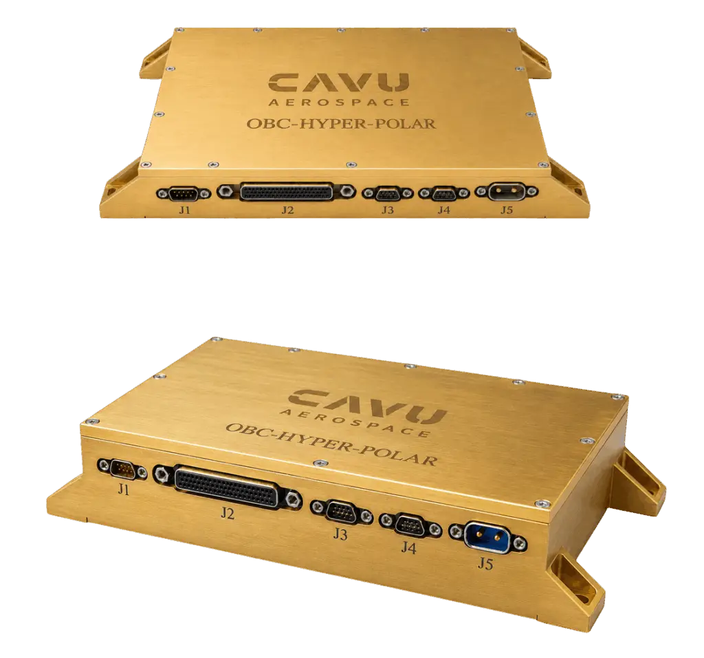
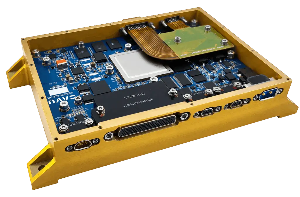
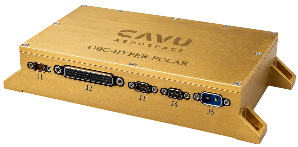
The OBC-Hyper Polar is a cutting-edge onboard computer specifically designed for critical space missions with considerable onboard processing. Leveraging Microchip PolarFire SoC FPGA technology, this space OBC provides exceptional performance and versatility for space applications. Whether your mission involves scientific research, Earth observation, or commercial satellite deployment, the OBC-Hyper-Polar ensures optimal performance and reliability in the harsh conditions of space. It comes with different variations COTS/ Rad. Tolerant & several peripheral boards.

MEETING COMPUTING NEEDS
- High-Performance Computing: Demanding applications like onboard image processing, data analysis, and autonomous operations.
- Complex Missions: Missions requiring extensive software frameworks, real-time operating systems, and diverse payload interfaces.
- Long-Duration Missions: Applications where reliability and radiation hardening are critical for long-term success.
MISSION CHOICE
If your mission demands high-performance computing, complex software frameworks, or long-duration reliability, the OBC-Hyper Polar is the answer. Its unmatched processing power, extensive memory options, comprehensive interface selection, and robust radiation hardening make it the ideal onboard computer for demanding space missions.
KEY FEATURES
- Microchip PolarFire SoC FPGA — two variants: MPFS250T (254k LE) & MPFS460T (461k LE)
- RISC-V MSS: 4× 64-bit U54 application cores + 1× E51 monitor core; >4,000 DMIPS
- Flash-based FPGA fabric — ZeroFIT SEU immunity; inherently non-volatile (no external boot PROM required)
- DDR4 SDRAM (Fabric) 8 GB 72-bit ECC Enabled
- LPDDR4 SDRAM (MSS) 4 GB 32-bit
- Dual 256 GB eMMC (one on MSS SDIO, one on fabric SDIO)
- Dual 512 Mbit QSPI NOR Flash (primary + redundant boot/config)
- 4 Mbit SPI MRAM SEU Immune
- 4× RS-422 full-duplex serial
- 4× RS-232 serial
- 4× CAN
- 4× RS-485
- 32× buffered GPIO (GPIOB [1…32]) in 4 banks + 8× buffered bidirectional I/O (IO [1…8]) + 8× Direct-IO
- 1× I2C
- 2× LVDS differential pairs (SpaceWire ECSS-E-ST-50-12C compatible)
- 2× Gigabit Ethernet
- Up to 4× additional GbE via 6-Ethernet addon card (total 6× GbE)
- 16-channel, 16-bit ADC (simultaneous sampling, ±5 V / ±10 V factory-selectable)
- USB 2.0 (PolarFire SoC native)
- USB-to-UART debug (dual channel)
- JTAG (FlashPro5/6 compatible)
- 8× SerDes transceivers (up to 12.7 Gbps each)
- Configurations: PCIe, CoaXpress, CSI-2, NVMe, USB3.0, Ethernet 10G
- Input voltage: 8 V to 28 V DC; OVP and UVLO factory-programmable
- 2-pin power connector (Glen Air GMPM2-B112R-CBRT-SU)
- Dual-redundant on-card DC-DC regulators
- Hardware watchdog timer
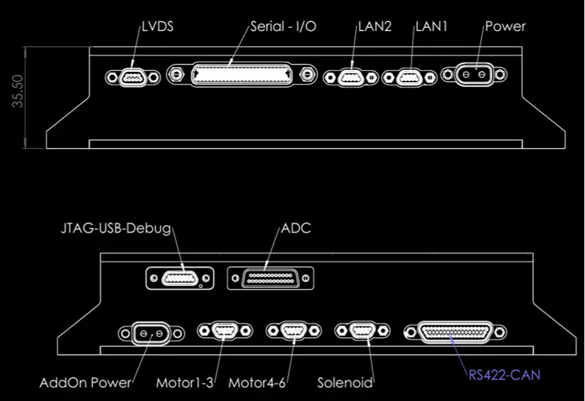
- Chassis: AL7075-T6, Dimensions: 110 × 181 mm, height: 22.5 mm / 35.5 mm
- Mass: 600 gr, <1,000 gr (with addon card)
- All I/O connectors: Micro-D (MIL-DTL-83513 family); Power connector: GlenAir GMPM2
- Software Support: Linux, FreeRTOS, Bare-Metal, etc.
- Paired with the NVIDIA Jetson Orin AGX 64GB for AI/ML Edge Computing. Typhoon Edge
- Radiation Tolerant Variations
- Double-OBC configuration
- Radiation Performance
- High-Power Driver Package for Solenoids, Stepper Motors, Actuators and Aux Loads
SPECIAL FEATURES
- Expected Life-time: 3 to 5 years in LEO
- On-Board Current & Temperature Monitoring
- On-Board Watchdog
- Double Redundant DC-DC
- TMR and Double Redundant Storage Options
- Custom Daughter Card Connection for SerDes
- Implementing Custom FPGA Processing Design Available
- QML-V & QML-Q Options Available
PROCESSOR
- Microchip PolarFire SoC Flash Based FPGA SoC
- Quad 64-bit RISC-V on FPGA + 1 RISC-V Monitoring Core
- 660MHz per Core offering more than total 4000DMIPS
- Free Eclipse-based SoftConsole Programming IDE and Debug via JTAG for the rapid development of bare metal- and RTOS-based C/C++ software
- Optional 32-bit RISC-V Soft Cores
ENVIRONMENT
- Radiation Tolerance:
- ZeroFIT SEU neutron-immune FPGA
- Total Ionizing Dose: More than 30Krad (Si)
- Internal Block RAM ECC Protected
- Latch-up Immune
- Temperature & Pressure: -40 C to +85 C @ 10-8 bar
- Random Vibration: 14.1 g rms qualification (QM); 10.0 g rms acceptance (FM); 3 axes, per ECSS-E-ST-10-03
- Sinusoidal Vibration: 5–100 Hz sweep, 3 axes; profile per spacecraft ICD
- Shock (SRS): 2,000 g over 100–10,000 Hz; 3 axes, both polarities
BUDGET
- Dimensions: 146×110×21 mm
- Mass : 600gr
- Power Supply : 5V ±5% or 8V~36V
- Power Consumption: 3W ~ 5W
SOFTWARE SUPPORT
- Design Tools:
- Operating Systems and RTOS:
- Linux, FreeRTOS, GNOME, INTEGRITY, FreeBSD, Azure, Ubuntu, VxWorks, SAFWRTOS, Yocto Project, etc.
PRODUCT DOCUMENTS
- Failure Modes, Effects, and Criticality Analysis (FMECA)
- Reliability Analysis Report
- Radiation Analysis Report
- Safety Assurance Plan
- Fault Tree Analysis (FTA)
- Single Point Failure Analysis (SPFA)
- Worst Case Analysis (WCA)
- Derating Analysis Report
- Availability Analysis Report
- Mechanical Analysis Report
- Maintainability Analysis Report
- Fault Detection, Isolation, and Recovery (FDIR)
- Qualification Test Plan (QTP)
- Environmental Test Reports, TVAC, Vib.
- EMC/EMI Test Report
- Radiation Test Report
- Operational Risk Assessment (ORA)
- Critical Items List (CIL)
- Materials, Processes, and Mechanical Parts List (MPMPL)
- Product Assurance Plan (PAP)
- Configuration Item Data List (CIDL)
- End Item Data Package (EIDP)
- As-Built Configuration List (ABCL)
PERIPHERALS / ADD-ON CARDS
- Multiple High speed CameraLink interface
- Serial interface support: Multi-UART or CAN bus card
- Sensor integration: IMU or magnetometer daughtercard
- Image processing: FPGA or GPU compute module
- Storage: SD card expansion or flash memory module
- Communications: S-band/UHF radio transceiver module
- Power management: MPPT or battery monitoring addon
- 6 Gb Eth peripheral board
- High-Power Drivers Package for multiple solenoids, stepper motors, actuators, Aux loads etc.
One add-on set, every current class: 8 solenoid channels at 0.25–0.75 A, 10 auxiliary channels at 7 A continuous / 10 A peak (relays, heaters, devices), 4 TVC actuator channels at 25 A — from a quarter-amp valve to a 25 A actuator on the same two cards.
(Could be increased to any number of outputs)Multi-hundred-amp class: 100 A on the 36 V bus plus 70 A on the 24 V bus, carried on 3 mm copper busbars and heavy-copper PCB, with sub-watt losses per bar.
Every channel individually protected: an eFuse controller per channel with a ≈ 1 µs short-circuit trip, programmable overload timer, under-voltage lockout and thermal latch with remote sensing of the FET bank.
Controlled turn-on for capacitive loads: a precharge stage starts a 25 A actuator at a resistor-set 60 A, independent of the load capacitance, and the main FET bank closes into a charged output with no inrush — verified against a 1100 A uncontrolled start.
Reverse-polarity immunity without a diode drop: an ideal-diode stage blocks a reversed supply completely (protected side stays at 0 V) and isolates the loads from a collapsing source in ≈ 7 µs, at 4–5 W loss for 100 A.
Compact EMI filtering: ceramic-only, ≤ 2.5 mm high, no magnetics — 24 / 34 / 44 dB at 1 / 3 / 10 kHz; a 60 A channel start moves the bus by only 2 V.
Power and sensing in one package: a dual 16-channel simultaneous-sampling ADC for pressure and analog sensors alongside a 16-channel 1 MSPS health ADC — per-channel current for all 22 outputs, bus voltage and temperatures.
Direct, deterministic control from the OBC-HYPER-POLAR: one FPGA enable per power channel through sacrificial buffers, SPI to the ADCs, I2C to the sensors; a channel can never turn on without a driven command.
Fail-safe by construction: enables default off during FPGA configuration, brown-out or a missing card; the power stage cannot back-power the OBC; buffers are the only thing between the FPGA and the high-voltage board.
Configurable at assembly, not by redesign: start current, protection thresholds, turn-off behaviour, release time, filter fit and grounding policy are fitted values set from a short interface questionnaire — the same boards serve different loads and buses.
Verified before hardware: SPICE with vendor device models for the FET banks, ideal-diode controller and high-side switches, harness and busbar parasitics included; every figure in the deck comes from a netlist that can be re-run.
Reliability Cost/ Worth COTS vs. RT
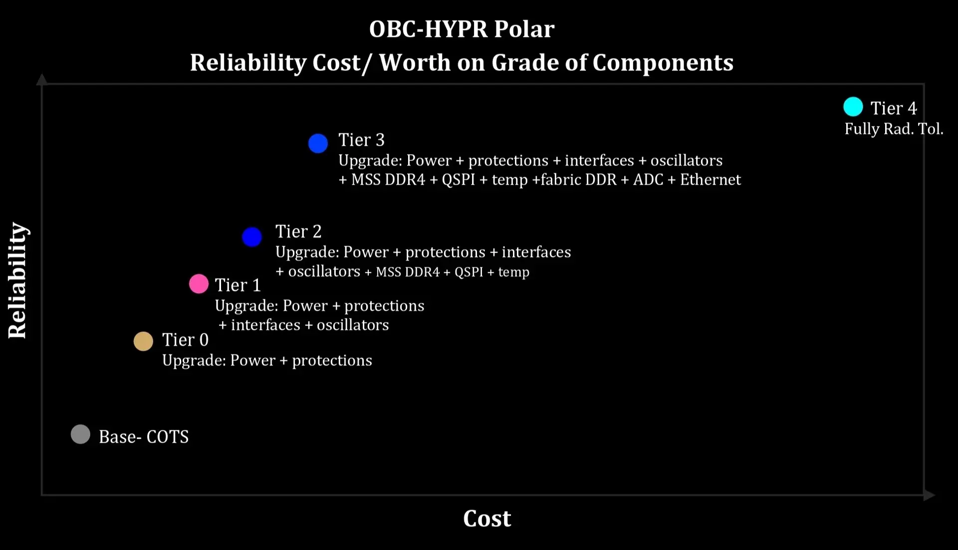
For flight models, a trade-off between reliability and cost is required. OBC-Polar is available in multiple configurations, including COTS-based, partially radiation-tolerant, and fully radiation-tolerant variants. The PolarFire SoC is inherently latch-up immune. For each configuration, component part numbers are shared and a detailed FMEA is performed to identify critical components and assess reliability vs. cost, providing full visibility of the available options to space missions.
Options:
- Baseline: All COTS components
- Tier0: Upgraded parts: Power + protections
- Tier1: Upgraded parts: Power + protections + interfaces + oscillators
- Tier2: Upgraded parts: Power + protections + interfaces + oscillators + MSS DDR4 + QSPI + temp
- Tier3: Upgraded parts: Power + protections + interfaces + oscillators + MSS DDR4 + QSPI + temp + fabric DDR + ADC + Ethernet
- Tier4- Fully Radiation Tolerant
Tier0 (Power / Protection)
- P/N → P/N -SEP class
Tier1 additions (Interfaces + Oscillators)
- P/N → P/N -SEP class
- LVDS: P/N → P/N -SEP class
- Oscillators: COTS XOs → Microchip space XO family
Tier2 additions (Boot / Memory / Sensors)
- P/N → P/N -SEP class
Tier3 additions (Fabric / ADC / Ethernet)
- Fabric DDR: P/N →P/N -SEP class
- ADC: P/N → RT/space ADC option
- Ethernet PHY: P/N → Microchip rad-tolerant GbE PHY option
DUAL-OBC REDUNDANCY
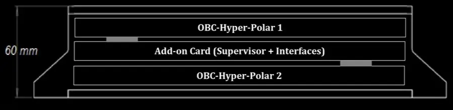
In a typical redundant architecture, the spacecraft contains:
- OBC-A
- OBC-B
- A dedicated Supervisor
- Controlled power paths
- Reset and enable signals
- Health-monitoring interfaces
- Communication interfaces between the Supervisor and each OBC
At any given time, one OBC can operate as the Active OBC, responsible for controlling the spacecraft and executing the primary mission or platform software. The second unit can remain in one of several states, depending on the mission requirements:
- Cold redundancy – the backup OBC is completely powered off.
- Warm redundancy – selected circuits or subsystems remain powered, allowing faster activation.
- Hot redundancy – both OBCs are powered and operational, with one designated as the active controller.
The Supervisor provides the mechanism required to manage these states safely and predictably.
BOARD SUPPORT PACKAGE
- Microchip MSS drivers (mpfs-hal, mss-can, mss-ethernet-mac, mss-gpio, mss-i2c, mss-mmc, mss-mmuart, mss-pdma, mss-qspi, mss-rtc, mss-spi, mss-sys-services, mss-timer, mss-usb, and mss-watchdog)
- Microchip FPGA IP core drivers (x40 RS422 UART, CAN, RS485, RS232, ADC, CoreMMC, PF_PCIe, GPIO)
- Custom drivers developed for HYPER peripherals and interfaces
- A test application platform to evaluate HYPER performance
- Comprehensive SoftConsole test projects to verify the performance of critical modules, including Ethernet and DDR memory
BARE-METAL
- Microchip MSS drivers (mpfs-hal, mss-can, mss-ethernet-mac, mss-gpio, mss-i2c, mss-mmc, mss-mmuart, mss-pdma, mss-qspi, mss-rtc, mss-spi, mss-sys-services, mss-timer, mss-usb, and mss-watchdog)
- Microchip FPGA IP core drivers (RS422 UART, CAN, RS485, RS232, ADC, CoreMMC, PF_PCIe, GPIO)
- Custom drivers developed for HYPER peripherals and interfaces
- A test application platform to evaluate HYPER performance
- Comprehensive SoftConsole test projects to verify the performance of critical modules, including Ethernet and DDR memory
YOCTO
- HSS SoftConsole project for HYPER
- A Yocto layer for HYPER built on top of Microchip’s main Yocto BSP
- Documentation for creating a HYPER image
- MSS and fabric device tree files