Transformerless Ethernet using Capacitive Coupling in Embedded and Backplane Systems
- February 2, 2026
- CAVU Aerospace UK
- Introduction
Ethernet interfaces traditionally use magnetics (transformers) to provide galvanic isolation and common-mode noise rejection. However, in tightly integrated embedded systems or backplane designs, transformerless Ethernet becomes desirable due to:
- Board space limitations
- Cost and height constraints
- Lack of isolation requirement (e.g., shared ground plane)
This note explains the principles of transformerless Ethernet using AC coupling, with a focus on the differences between voltage-mode and current-mode PHY drivers, and details practical implementation strategies.
- Ethernet Line Driver Architectures
Ethernet PHYs use one of two driver architectures to transmit data differentially: voltage-mode or current-mode.
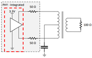
2.1 Voltage-Mode Line Drivers
- Definition: Voltage-mode drivers actively drive a voltage swing across the transmission line.
- Characteristics:
- Low output impedance
- Often include internal 50-ohm termination
- Self-biased (no need for external common-mode voltage)
- Suitable for AC-coupled operation
- Examples of compatible standards:
- 1000BASE-KX (IEEE 802.3ap) – Backplane Ethernet
- 1000BASE-CX (IEEE 802.3z does not mandate voltage-mode driver architecture; PHY vendors may choose either) – Short-reach copper links (up to 25 m)
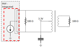
2.2 Current-Mode Line Drivers
- Definition: Current-mode drivers source or sink a constant current, developing a voltage across external termination.
- Characteristics:
- High output impedance
- Requires external termination resistors
- Requires external bias voltage (typically via pull-up resistors to 2.5 V or VDD)
- Not naturally compatible with AC coupling without additional circuitry
- Examples of compatible standards:
- 1000BASE-T (IEEE 802.3ab) – Gigabit Ethernet over twisted pair (RJ45)
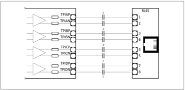
- Transformerless Ethernet via Capacitive Coupling
AC coupling using capacitors allows transformerless Ethernet connections by blocking DC components while preserving the differential AC signals. This is particularly effective in:
- PCB backplanes
- On-board communication between two PHYs or MAC-PHY connections
- Systems with shared ground references
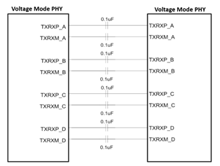
3.1 Voltage-Mode PHY ↔ Voltage-Mode PHY
- Required Components: Just series AC coupling capacitors (typically 100 nF X7R).
- Termination: Provided internally by the PHY.
- Biasing: Managed internally; no external biasing required.
- Applications:
- Compact embedded systems
- Multi-board systems with backplane traces
3.2 Current-Mode PHY ↔ Current-Mode PHY
- Required Components:
- Series AC coupling capacitors
- External 50-ohm pull-up resistors to 2.5 V or VDD on each differential signal line
- Termination: Must be provided externally.
- Biasing: Required to establish correct common-mode voltage.
- Risks: Improper biasing may lead to degraded signal quality or link failure.
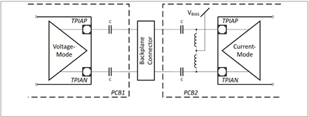
3.3 Voltage-Mode PHY ↔ Current-Mode PHY
- Asymmetric Configuration:
- Voltage-mode side: AC coupling only
- Current-mode side: Requires external pull-up resistors for biasing
- Use Case: Typically discouraged unless validated via simulation or test due to mismatch in drive behavior
- Standard Ethernet Configurations vs. Transformerless Operation
IEEE Standard | Media Type | Driver Type | Max Length | Transformerless Feasible? | Notes |
1000BASE-T | Cat 5e/6 Twisted Pair | Current-mode | 100 m | No | Requires magnetic isolation |
1000BASE-CX | Shielded Copper (Twinax) | Voltage-mode * | 25 m | Yes | Short-reach, DC-coupled or AC-coupled |
1000BASE-KX | PCB Backplane | Voltage-mode | ~1 m | Yes | Designed for transformerless usage |
*Actual driver depends on implementation.
- Notes on RJ45 and Mixed Interfaces
When connecting a capacitive-coupled PHY to an RJ45 transformer-coupled port, consider the following:
- Isolation mismatch may violate IEEE 802.3 safety standards
- Common-mode voltage differences can degrade performance
- Use magnetics modules or integrated RJ45 jacks for proper coupling.
- Recommendations
Choose Voltage-Mode PHYs with Internal Termination and AC-Coupling Support:
- Voltage-mode drivers are designed to drive a defined voltage swing across the differential pair, and they control their own common-mode output voltage, making them naturally compatible with AC-coupling.
- Internal termination (e.g., 100 Ω differential impedance built into the PHY) simplifies board layout and ensures proper signal reflections are suppressed—critical in high-speed links like Gigabit Ethernet.
- If AC coupling is not documented, the PHY may expect a fixed DC bias at its input, and coupling capacitors may lead to incorrect voltage levels or link failure.
- Conclusion: This combination ensures clean signal operation without the need for biasing resistors or transformers, leading to reliable and compact PCB designs, especially in space, automotive, or backplane systems.
Use 1000BASE-KX or 1000BASE-CX PHYs for backplane and internal Ethernet:
- 1000BASE-KX (IEEE 802.3ap) is explicitly designed for backplane transmission over PCB traces, with AC coupling and transformerless operation defined in the standard. It mandates voltage-mode signaling and supports equalization and link training.
- 1000BASE-CX (IEEE 802.3z) uses shielded 150-ohm copper cable, often for rack-level interconnects, and is also based on voltage-mode drivers. While transformerless operation isn’t explicitly mandated, many implementations (especially SFP+ Direct Attach) omit magnetics in short-distance links.
- Conclusion: These standards and their PHY implementations are inherently suited to transformerless, space- and height-constrained designs (e.g., satellites, automotive modules, or high-speed control boards).
Avoid transformerless configurations with 1000BASE-T or current-mode PHYs unless the design is well characterized.
- 1000BASE-T (IEEE 802.3ab) is designed for long-distance twisted-pair cabling (up to 100 m) and requires:
- Galvanic isolation via transformers (per IEEE safety requirements).
- Current-mode drivers, which do not define a common-mode voltage and instead rely on external termination and biasing.
- Using capacitors alone with current-mode PHYs can lead to:
- Floating input nodes (causing noise and false signaling).
- Inconsistent common-mode levels, increasing bit error rates.
- Potential damage if DC imbalance or overshoot occurs.
- If transformerless use is attempted with 1000BASE-T, it requires explicit design for biasing, termination, and link compatibility, often only done in closed systems with known PHY pairs.
- Conclusion: Without exhaustive testing, such configurations are electrically risky and non-compliant with Ethernet safety standards. Avoid them unless the system is fully characterized and operates in a controlled environment (e.g., custom internal links in space hardware).
Validate mixed configurations using simulation tools or prototype testing.
- Mixed-mode connections (e.g., voltage-mode PHY ↔ current-mode PHY) or non-standard configurations (e.g., AC-coupled 1000BASE-T PHY ↔ RJ45) involve:
- Differences in impedance, common-mode behavior, and termination expectations.
- Risk of link negotiation failures or silent data corruption.
- Signal integrity (SI) tools such as HyperLynx, ADS, or SPICE-based simulations can model AC coupling, line impedance, and signal swing.
- Prototype validation using real PHYs and test cables helps verify link training, auto-negotiation, and packet loss under real EMI and loading conditions.
- Conclusion: Even in voltage-mode-to-voltage-mode cases, signal reflections, board layout, and return loss must be verified. For mixed or edge cases, simulation and lab testing are essential for production confidence.