Radiation Tolerance of OnBoard Computers Analysis & TID Test Procedures
- January 28, 2026
- CAVU Aerospace UK
Introduction
Spacecraft electronics are continuously exposed to energetic particles originating from:
- the Earth’s radiation belts,
- solar particle events,
- galactic cosmic rays.
These particles interact with semiconductor devices and cause:
- Cumulative degradation over time &
- Instantaneous faults during operation.
Both effects must be considered when designing onboard computers.
With the rapid growth of the commercial space sector, there is a clear industry shift toward the use of commercial off-the-shelf (COTS) components, driven by long procurement lead times, limited availability, and high cost of traditional radiation-hardened parts. To remain competitive and responsive to mission schedules, manufacturers must therefore adopt radiation-tolerant-by-design (RTBD) methodologies that enable reliable operation using predominantly commercial integrated circuits. This approach requires rigorous radiation environment analysis, shielding assessment, and formal verification through radiation testing in order to quantify design margins and provide customers with objective, traceable evidence of system-level radiation robustness.
Total Ionizing Dose (TID)
TID represents the cumulative damage caused by ionizing radiation in semiconductor materials over the mission lifetime.
Effects include:
- threshold voltage shifts,
- increased leakage current,
- timing degradation,
- functional failure.
TID is measured in: rad (Si) or krad(Si)
Single Event Effects (SEE)
Single energetic particles can cause:
- bit flips (SEU),
- latch-up (SEL),
- functional interrupts (SEFI),
- destructive events (SEB/SEGR).
These are handled using architectural and design mitigation techniques and are treated separately from TID.
Radiation tolerance of COTS-based computers
Computers with COTS components used either in EM, QM or FM are immune to radiation range of 10 to 30 krad. We have some design techniques to improve tolerance for COTS-based computers.
- Triple-modular redundancy
Its a fault-tolerant design technique in which three identical instances of a function operate in parallel, and their outputs are continuously compared using a majority-voting mechanism.
It is widely used in space electronics to mitigate SEE and to improve overall system reliability in radiation environments.
- Latch up protection
Latch-up protection systems detect abnormal current consumption and rapidly remove power from the affected device or rail. The protection cycle is: Monitor current on the power rail or device supply, detect over-current exceeding a predefined threshold, disconnect power within microseconds to milliseconds, allow cool-down, restore power & log the event.
Common implementation techniques are: Electronic current limiting, Power rail segmentation, Automatic power cycling, Dedicated latch-up protection ICs, Thermal protection
- ECC & EDAC
These are techniques used to protect digital memory and data paths from corruption caused by radiation-induced faults, particularly SEUs. The most common implementation in onboard computers are: Single Error Correction, Double Error Detection, Corrects 1-bit error, Detects 2-bit errors, Widely supported by space-grade MCUs, FPGAs, and memory controllers, Double Error Correction, BCH codes & Reed–Solomon (for mass memory).
- Screening
- Thermal margining
- Over design
- Using Rad. tol. ICs for critical components
For each OBC, as part of system engineering at sub-system level, we carry out FMEA to recognize critical components and list critical items. Usually DC-DC & Storages are critical components in COTS-based OBCs as FPGAs have tolerant design by manufacturers.
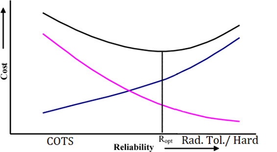
Final cost would be between COTS & Rad. tol. Component but effectively improve sub-system reliability.
As a manufacturer, we provide a comprehensive radiation analysis report as part of our subsystem engineering process. This includes an assessment of reliability versus cost, giving our clients a clear view of trade-offs and enabling informed decisions to optimize system reliability.
Test & Verification
Radiation tolerance is determined using controlled irradiation tests performed according to international standards such as:
- ESCC 22900 (Europe),
- MIL-STD-883 TM1019 (US),
- ECSS Radiation Hardness Assurance methodology.
While the standard defines available options and procedures, the specific test profile is determined by the client. Due to costs, project managers need to make decision on test profiles. Testing can be performed at:
- Board-level (Computer without AL enclosure box)
- Sub-System level (Computer with AL enclosure box with different thicknesses)
- Both Board & Sub-System level
In these tests, electronics are powered and monitored, parameters are measured during irradiation and then degradation is tracked until failure or beyond mission dose.
Mechanical enclosures provide significant radiation shielding.
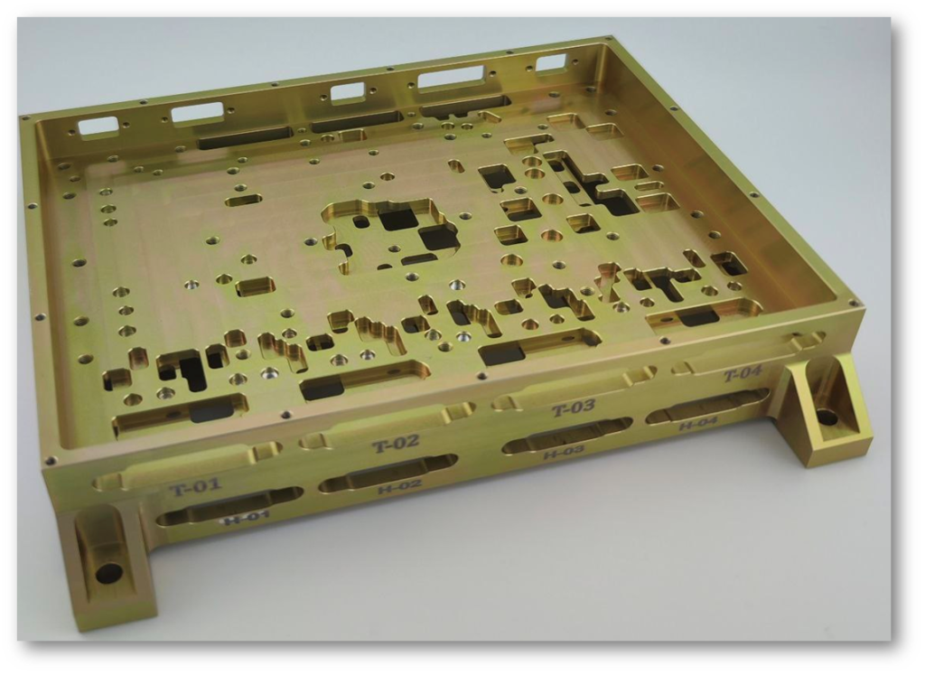
OBCs usually are delivered with AL7075-T6 enclosure box with 0.01mm precision cutting to help with physical protection, thermal management & radiation protection. At the subsystem level, we account for the OBC enclosure and any additional shielding surrounding its location when performing radiation analysis.
Aluminium enclosure can reduce the radiation dose reaching internal electronics by a factor of 2 to 10 depending on thickness, orbit and particle spectrum. Thickness is usually 4 mm to 10 mm.
The standard outlines the recommended procedures, while the client determines the specific test profiles based on budget, schedule, and mission reliability requirements. Best practice for radiation tests is therefore:
- Test at board level (without enclosure box)
- Apply shielding by analysis
- Test at Sub-System level (With enclosure box- Optional)
For deep space missions answer is easy, but for missions in GEO or several years in LEO, clients seeking guidance on maximizing value from mission budget—whether choosing between COTS or radiation-tolerant components, or planning radiation testing—we recommend following the procedures outlined below:
- Determine the mission minimum TID requirement
LEO: 20–50 krad, GEO: 50–150 krad
- Evaluate the feasibility of a COTS-based OBC architecture and perform FMEA
- Assess implementation options: fully COTS-based, partially radiation-tolerant, or fully radiation-tolerant subsystem.
- Evaluate mission parameters, including orbit, launch profile, and the physical location of the OBC within the spacecraft.
- Perform radiation analysis at both board and subsystem levels.
- Conduct TID testing at board level.
- Estimate subsystem-level TID using shielding and geometry analysis.
- Where feasible, perform subsystem-level TID testing for final verification.
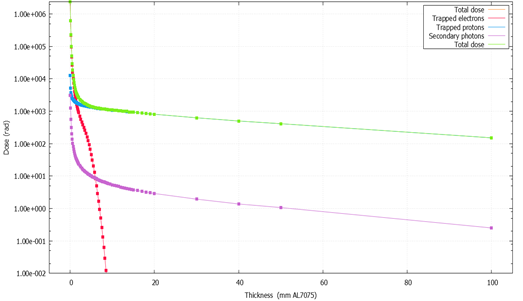
For example, a TID test was conducted on OBC-1 which is SmartFusion-2 FPGA computer & a storage component was stopped at 24 kRad. Shielding effectiveness depends strongly on orbit & particle energy spectrum. With 6 mm AL shielding in LEO, TID tolerance will be 48-72 kRad for a LEO mission.
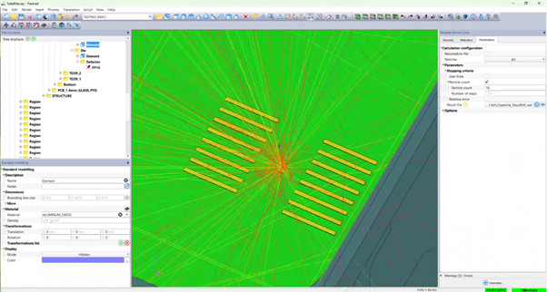
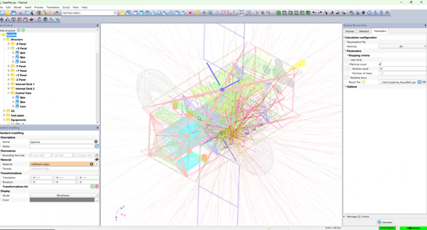
More accurate estimates can be achieved through detailed radiation analysis. This requires only the mission orbit parameters, launch profile, and a STEP (.stp) file of the spacecraft structure showing the intended OBC installation location. Results can guide clients to identify critical points & get max value from mission spending.