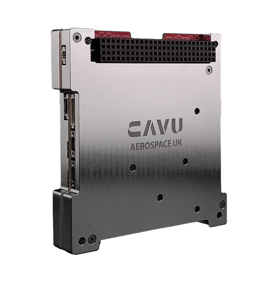
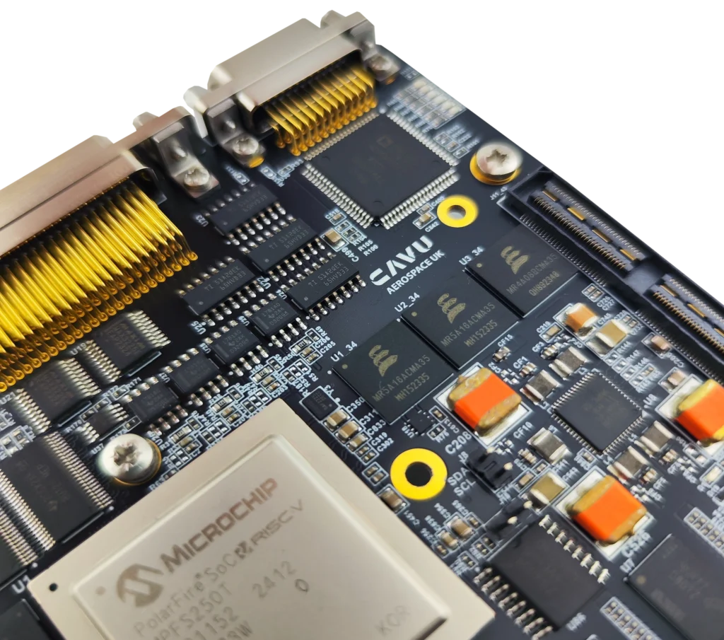
A quick insight into the facts behind our products’ reliability and processing power: Polar Edge
A quick insight into the facts behind our products’ reliability and processing power: Polar Edge Microchip’s flash-based PolarFire FPGA SoC combined with NVIDIA Jetson processors
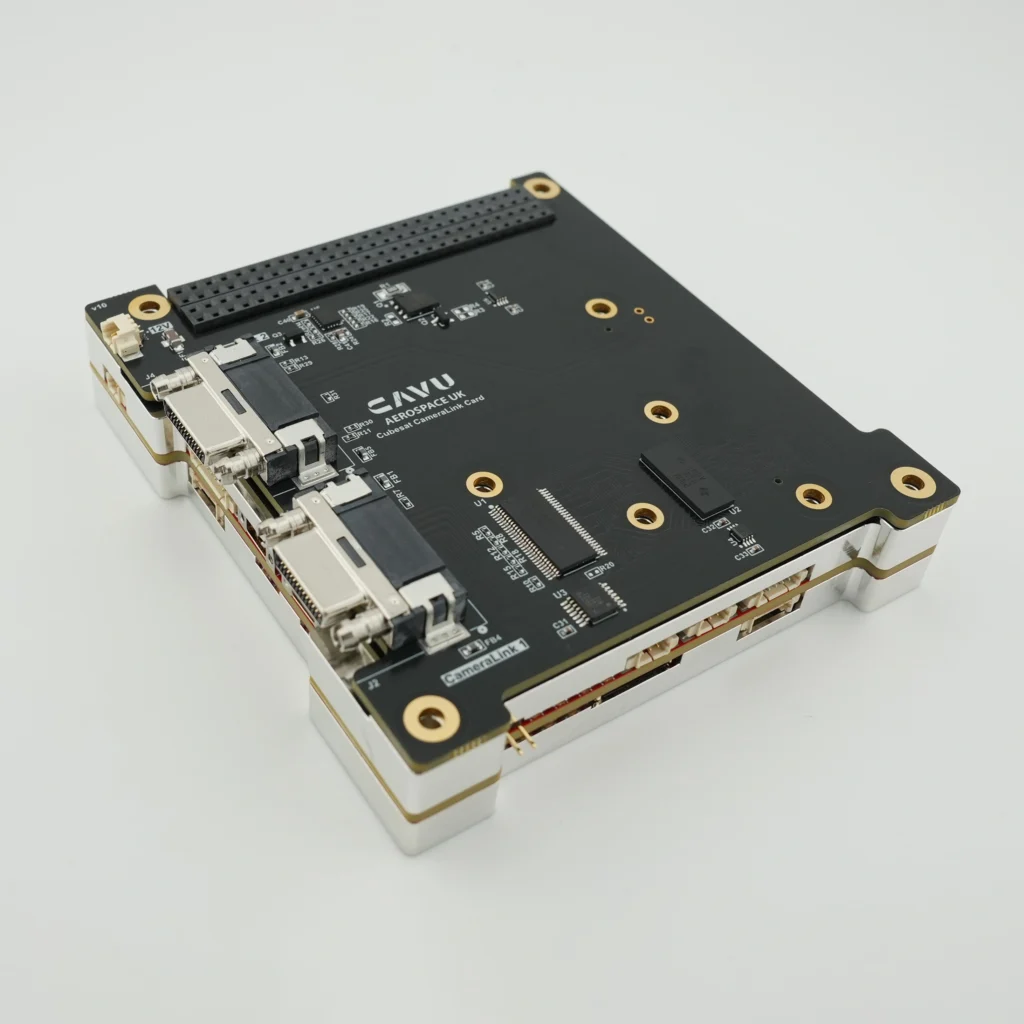
CAVU Aerospace custom daughterboards on OBCs
Addon cards can significantly improve the interface capabilities of a CubeSat onboard computer by expanding its functionality, enhancing data acquisition, and supporting mission-specific hardware. Here’s
OBC-Polar Rockets Flight Computers, When precision in PCB matters
Flight computers are used in aircraft, spacecraft, drones, and satellites where every cubic centimetre is precious. Design is always a compromise of different constraints: Size

Latch-Up Protection – Phenomenon and Strategy
Latch-up in CMOS technology is caused by ionizing particles (e.g., heavy ions) creating parasitic paths between power and ground, often forming a parasitic SCR (thyristor
Transformerless Ethernet using Capacitive Coupling in Embedded and Backplane Systems
Transformerless Ethernet using Capacitive Coupling in Embedded and Backplane Systems Ethernet interfaces traditionally use magnetics (transformers) to provide galvanic isolation and common-mode noise rejection. However,

Product Development Journey
When we say a product is developed, we truly mean it! Nearly all CAVU Aerospace products come with comprehensive analytical reports since 2017. These documents
OBC Radiation Analysis, COTS or Rad-Tol. components ?
For low earth orbit missions, there is always a question how to choose among Rad-Hard, Rad-Tol & COTS components for satellite & launch vehicle avionics.
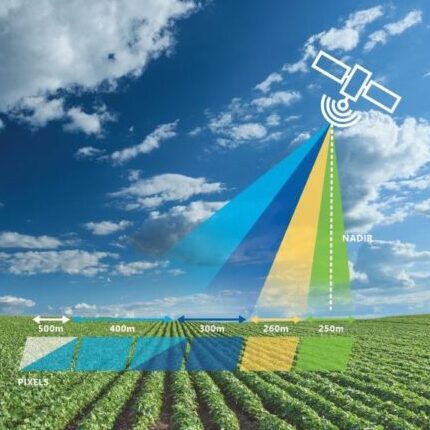
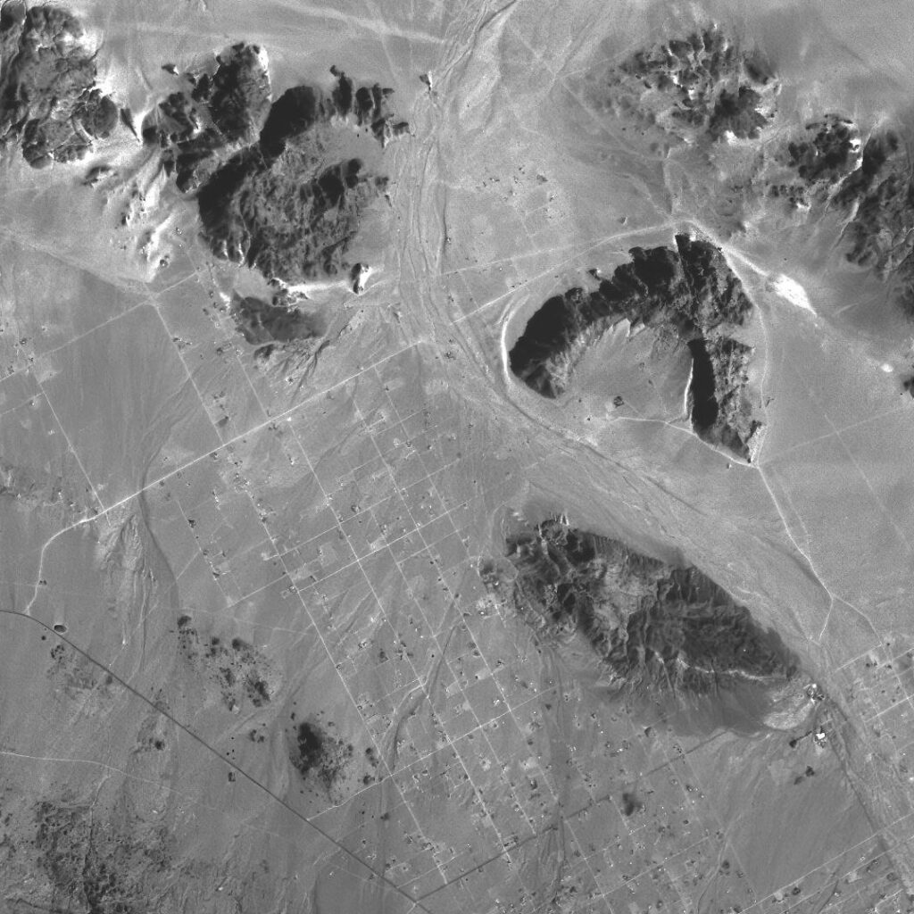
Space data for environmental monitoring will be in much better place in 2025
ESA Biomass satellite will be launched in few days, uses P-band SAR data. P-band SAR data helps monitor trees by using its long wavelengths to

OBC enclosure box
🚀 When Do We Really Need Enclosure Boxes for PCBs in Satellite and Launch Vehicle Systems? In the mechanical integration of On-Board Computers (OBCs) within
Automated PCB routing, CAVU’s Technical Advantage for Fast Lead Times
Automated PCB routing, CAVU’s Technical Advantage for Fast Lead Times There’s always a reason behind quicker lead times and more competitive prices —it’s the technical

CAVU Aerospace shortlisted for Scotland Technology Award, 2025
CAVU Aerospace shortlisted for Scotland Technology Award, 2025 CAVU Aerospace delivered few groundbreaking projects to industry giants. It involves more than 15 Scottish companies in
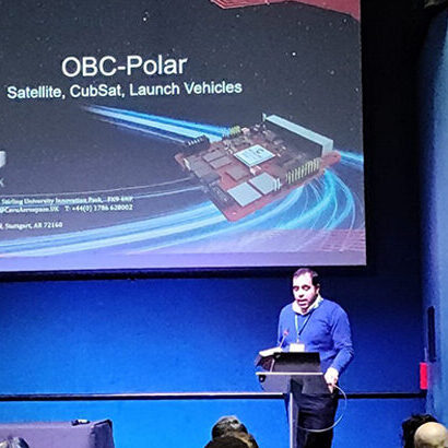
CAVU Aerospace Showcase OBC Polar at Ignite Space, Leicester 2025
CAVU Showcase OBC Polar in Ignite Space 2025-Leicester CAVU Aerospace UK was proud to participate in the Technology Showcase at Ignite Space 2025, where we
The Challenge of AI Processing in Space
As AI technology advances, the demand for onboard processing in CubeSats and small satellites is growing. This article delves into the challenges of AI edge computing in space, particularly the radiation vulnerabilities of NVIDIA Jetson processors, and how CAVU Aerospace UK is pioneering solutions with their Tartan Series Edge Computers.

The Demands of Space Edge Computing
The Demands of Space Edge Computing CAVU Aerospace UK, 2024 – As the space industry rapidly evolves, the demand for robust and efficient space edge