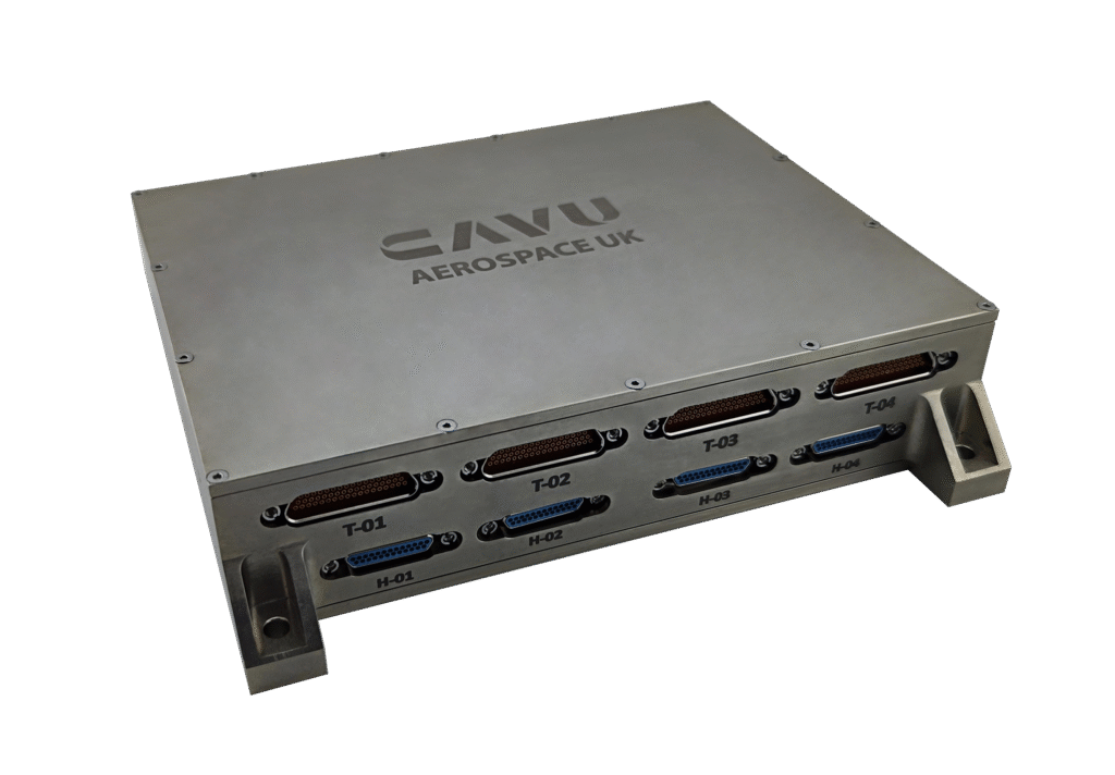
INSTRUMENT CONTROL UNIT - ( ICU )
Instrument Thermal Control & Payload Data Processor in Single Sub-System
PIONEERING SPACECRAFT COMPUTING
The ICU provides centralized and autonomous management for spacecraft payloads, including OMA and Auxiliary Camera subsystems, and sensor interfaces. The system is built upon a COTS or radiation-tolerant PolarFire FPGA SoC platform, ensuring robust performance, low power consumption, and high reliability.
KEY FEATURES
- Radiation-tolerant components and TID monitoring.
- Integrated FPGA co-processing capabilities.
- Autonomous thermal management.
- Dedicated power distribution and monitoring circuits.
- Fault detection, isolation, and recovery (FDIR) capabilities.
- Redundant communication interfaces ensuring reliable data transfer.
INTERFACES & DATA COMMUNICATION
- SpaceWire Interfaces: Main and redundant backup interfaces for reliable communication with the OMA subsystem. Main and Redundant communication with the PLHU platform. Main and redundant interfaces for auxiliary camera.
- CAN Bus Interfaces: Telemetry and telecommand communication with the PLHU subsystem. Additional redundant CAN interfaces for mission expansion and fault tolerance.
- RS422 Interfaces: Multiple RS422 communication channels provided for robust data transfer, subsystem interfacing, and debugging purposes.
- Ethernet Interface: Ethernet port dedicated to debugging, software developments, and system diagnostics.
- Sensor Interfaces: Integrated radiation-tolerant ADC channels for temperature sensor readings and radiation monitoring.
- Heater Control Interfaces: PWM-controlled heater channels with built-in short-circuit and fault detection mechanisms.
- Power Interfaces: Dedicated regulated 12V DC power line for the OMA subsystem. Monitored and controlled power rails with independent latch-up protection.
PROCESSOR
- Processor Type: The ICU utilizes the PolarFire FPGA SoC for all versions: PFM/QFM/FM versions: Radiation-tolerant version of the PolarFire FPGA SoC. EM version: Standard PolarFire SoC.
- Core Configuration: The PolarFire SoC features 5 RISC-V processors, which can operate either independently or in a lock-step configuration for fault-tolerant operation. The combined processing power of all cores can reach up to 4000 DMIPS.
- Operating Systems Supported: The system supports a range of real-time operating systems (RTOS), including: FreeRTOS (lightweight RTOS), Linux (for more complex tasks) and Bare-metal (for low-level control).
- The processors can run independently or in lock-step mode depending on mission requirements.
- Open-Source Toolchains: The ICU leverages open-source development and debug toolchains, available for both Windows and Linux hosts. These tools support development and debugging for RISC-V processors and FPGA fabric components.
- Custom Co-Processing: The FPGA fabric of the PolarFire SoC can implement custom co-processing cores to offload specific computations from the main processors to the fabric side, enabling flexible, high-performance computation with ease of use in user space
FUNCTIONS
- Real-time data acquisition and processing from sensors, including temperature and radiation sensors.
- Autonomous heater control loops based on configurable temperature set points and profiles.
- Robust power management and latch-up protection.
- Secure firmware updates, remote image management, and rollback mechanisms.
- High-precision timing synchronization through onboard RTC.
- Housekeeping data collection, logging, and telemetry reporting.
- FPGA-based custom computational offloading and acceleration.
HOUSEKEEPING & DIAGNOSTICS
-
The ICU autonomously manages system health through comprehensive housekeeping routines that monitor:
- Internal temperatures and sensor health.
- Voltage and current across multiple domains.
- Radiation exposure levels (TID).
- Heater functionality and thermal management effectiveness.
- Real-time logging of system health metrics, supporting fault detection and preventative maintenance.
MEMORY & STORAGE
- Radiation-Tolerant MRAM: The ICU utilizes radiation-tolerant MRAM chips to ensure reliable non-volatile memory storage in space environments. This memory is ideal for storing mission-critical data and software. We may also use MRAM as RAM.
- Radiation-Tolerant Flash Storage: For data storage and program image storage, the ICU integrates radiation-tolerant Flash memory to ensure reliable long-term data retention.
- Optional Radiation-Tolerant DDR4: Radiation-tolerant LPDDR4 may be included if required for specific high-bandwidth applications. However, this is not required for the current application and can be implemented based on mission-specific needs.
TEMP. SENSOR & HEATER CONTROL
- Temperature Sensing and Control: The ICU integrates radiation-tolerant ADC circuitry for accurate temperature sensor readings. These temperature readings are transmitted to the PolarFire SoC for processing and thermal control.
- Heater Control: Heater driver circuitry will be implemented as needed, either on a separate board or integrated into the processor board, depending on the mechanical and enclosure design. The system supports a double-stack configuration, integrating 12V power circuitry for the OMA camera and the heater driver circuitry.
REDUNDANCY & LATCH-UP DETECTION
- Redundant power paths will be implemented to ensure system stability in the event of power failure.
- Latch-up detection and recovery mechanisms will be implemented onboard to protect against transient errors and to ensure the ICU operates reliably in a radiation-prone environment.
RADIATION DETECTION
- Radiation Monitoring: The ICU will include radiation detection sensors onboard to continuously monitor the Total Ionizing Dose (TID) levels. These sensors will provide real-time data to the system for radiation environment monitoring.
- This radiation data will be used for system protection and to track any potential radiation-induced degradation.
PRODUCT DOCUMENTS
ICU is flight proven onboard computer for number of satellite projects and we have full ECSS/ NASA documentation documents & test reports.
- Failure Modes, Effects, and Criticality Analysis (FMECA)
- Reliability Analysis Report
- Radiation Analysis Report
- Safety Assurance Plan
- Fault Tree Analysis (FTA)
- Single Point Failure Analysis (SPFA)
- Worst Case Analysis (WCA)
- Derating Analysis Report
- Availability Analysis Report
- Mechanical Analysis Report
- Maintainability Analysis Report
- Fault Detection, Isolation, and Recovery (FDIR)
- Qualification Test Plan (QTP)
- Environmental Test Reports, TVAC, Vib.
- EMC/EMI Test Report
- Radiation Test Report
- Operational Risk Assessment (ORA)
- Critical Items List (CIL)
- Materials, Processes, and Mechanical Parts List (MPMPL)
- Product Assurance Plan (PAP)
- Configuration Item Data List (CIDL)
- End Item Data Package (EIDP)
- As-Built Configuration List (ABCL)
BUDGET
- Dimension: 180*150*50 mm
- Mass: 1.85 kg


