A Modular PolarFire SoC FPGA-Based Command & Data Handling Solution for Rockets
- July 3, 2026
- CAVU Aerospace UK
Modern launch vehicles demand avionics platforms capable of deterministic real-time processing, high channel-count data acquisition, and reliable power distribution for mission-critical actuators. The OBC-HYPER-Polar Command & Data Handling (C&DH) system has been developed as a modular, FPGA-based flight computer centered on the Microchip PolarFire® SoC FPGA. The architecture combines a high-performance on-board computer with a dedicated peripheral (add-on) board that significantly expands sensor acquisition and actuator control while maintaining a compact footprint suitable for rocket applications.
The modular approach enables a single avionics platform to support propulsion monitoring, guidance and control, telemetry, and vehicle health management across sounding rockets, sub-orbital launch vehicles, and reusable rocket systems.
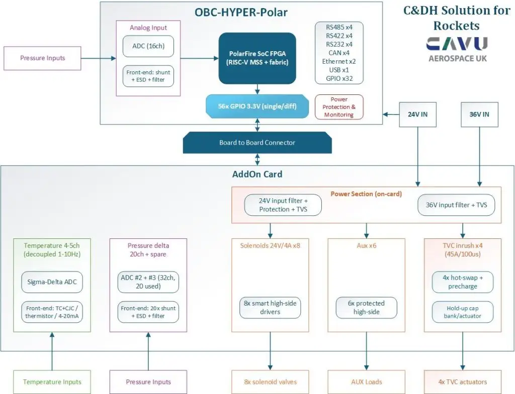
OBC-HYPER-Polar modular Command & Data Handling architecture
System Overview
The system consists of two primary assemblies:
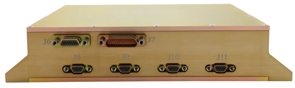
- OBC-HYPER-Polar Main Flight Computer
- Peripheral (Add-on) Board
The two boards communicate through a high-speed board-to-board interface, allowing the processing hardware and mission-specific I/O to remain physically separated. This modular architecture simplifies manufacturing, maintenance, and future upgrades while allowing different mission configurations to reuse the same core flight computer.
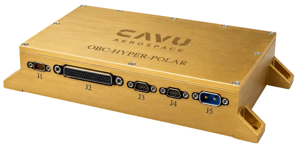
OBC-HYPER-Polar Main Flight Computer
At the heart of the system is the Microchip PolarFire® SoC FPGA, combining a multi-core RISC-V Management Subsystem (MSS) with a deterministic FPGA fabric.
Unlike conventional MCU-based flight computers, the FPGA architecture allows multiple acquisition and control functions to execute simultaneously without processor scheduling delays. Critical interfaces, actuator control logic, and high-speed sensor acquisition are implemented directly within FPGA logic, while higher-level mission software executes on the embedded RISC-V processors.
The flight computer integrates:
- 16-channel analog acquisition
- Front-end signal conditioning with shunt inputs, ESD protection, and filtering
- 56 configurable GPIOs (single-ended and differential)
- RS-485 (×4)
- RS-422 (×4)
- RS-232 (×4)
- CAN bus (×4)
- Dual Gigabit Ethernet
- USB interface
- Power monitoring and protection
This interface set provides connectivity for telemetry systems, navigation sensors, engine controllers, payload electronics, and ground support equipment without requiring additional interface hardware.
Peripheral (Add-on) Board
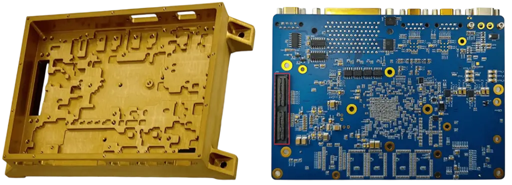
The peripheral board design has now been closed at the concept level. System-level analysis confirms that the complete analog acquisition and power electronics can be implemented on a single PCB measuring approximately 100 × 140 mm, providing substantial expansion of both sensor inputs and actuator outputs while sharing the processing resources of the main OBC.
The add-on board extends the capabilities of the flight computer in four principal areas.
Pressure Measurement
The base OBC already incorporates 16 analog input channels.
The peripheral board adds:
- 20 additional pressure channels
- One spare input
- Acquisition using AD7616-class 16-bit simultaneous-sampling ADCs
- Complete front-end conditioning with precision shunts, ESD protection, and analog filtering
Together, the complete system supports 36 channels of 4–20 mA pressure measurements, all acquired through the common FPGA acquisition engine.
This architecture provides sufficient capacity for engine instrumentation, propellant tank monitoring, pneumatic systems, and structural pressure measurements without requiring multiple acquisition modules.
Temperature Measurement
Temperature measurements are implemented using a dedicated high-resolution sigma-delta acquisition subsystem based on an AD7124-class converter.
The proposed architecture supports:
- 4–5 temperature channels
- Thermocouples
- Cold Junction Compensation (CJC)
- NTC/PTC sensors
- 10 kΩ resistive sensors
Because temperature varies significantly more slowly than pressure, these measurements are intentionally separated from the high-speed control loop and acquired at a configurable scan rate between 1 and 10 Hz, reducing computational load while maintaining excellent measurement accuracy.
Open item for confirmation: the Hardware Requirements Document (HRD) specifies five temperature channels, whereas earlier project documentation referenced four. Final channel count should be confirmed before schematic completion.
Solenoid and Auxiliary Outputs
The power output section provides the digital actuation required for propulsion and vehicle systems.
The current concept includes:
- 8 smart high-side solenoid drivers
- Rated at 24 V / 4 A
- Integrated protection and diagnostics
In addition, the board incorporates:
- 6 protected auxiliary high-side outputs
These outputs collectively satisfy the HRD requirement for 18 Power MOSFET GPIO channels, allocated as:
- 8 solenoid outputs
- 4 TVC outputs
- 6 auxiliary outputs
Confirmation requested: this interpretation assumes that the 18 MOSFET GPIOs represent the total available output population, rather than 18 additional channels beyond the listed functions.
TVC Power Conditioning
Thrust Vector Control actuators present demanding transient power requirements during motor startup.
To address these requirements, each actuator channel incorporates dedicated in-rush management consisting of:
- Individual hot-swap controller
- Local pre-charge circuitry
- Dedicated hold-up capacitor bank
- Supply from the 36 V power rail
Each channel is designed to tolerate approximately:
- 45 A in-rush current
- 100 μs duration
This localized architecture minimizes supply disturbances and prevents simultaneous actuator startup from causing voltage collapse on the vehicle power bus.
Power Architecture
The add-on board accepts both:
- 24 V input
- 36 V input
Each supply incorporates:
- Input filtering
- Transient Voltage Suppression (TVS)
- Protection circuitry
The 24 V rail powers the solenoid and auxiliary outputs, while the 36 V rail is dedicated to the higher transient demands of the TVC actuators.
Separating these domains improves system robustness and reduces conducted electrical noise between propulsion control and sensitive analog acquisition circuitry.
Interfaces
No additional communication interfaces are required on the peripheral board.
All external communications are provided by the standard OBC through its comprehensive complement of serial, CAN, Ethernet, USB, and GPIO interfaces. The peripheral board therefore functions as an intelligent I/O expansion module, with all sensor acquisition and actuator control synchronized by the PolarFire SoC FPGA.
Outstanding Design Items
While the concept has been validated, several system-level parameters require confirmation before progressing to detailed schematic capture and PCB layout.
- Analog Signal Domain and Filtering
For each of the 60+ analog input signals, the following design assumptions require confirmation:
- Ground reference strategy
- Whether sensor loops are vehicle-referenced or galvanically isolated
- Required anti-alias and bandwidth filtering for each sensor type
- Continuous and stall current requirements for the TVC actuators (in addition to the specified 45 A / 100 μs in-rush characteristic)
These parameters directly influence front-end protection, filter design, grounding architecture, and overall EMC performance.
- Control Loop Timing
The current assumption is that the primary flight control loop executes at:
- 600 Hz
- Approximately 1.67 ms per control cycle
Under this timing:
- Pressure acquisition comfortably supports the required sampling rate.
- Temperature is treated as a slow-varying parameter and scanned independently at 1–10 Hz.
Confirmation requested: temperature measurements are assumed not to participate directly in the 600 Hz closed-loop guidance and control algorithm.
The OBC-HYPER-Polar architecture demonstrates a scalable and highly integrated avionics solution for modern launch vehicles. By combining the deterministic processing capabilities of the Microchip PolarFire SoC FPGA with a compact, mission-specific peripheral board, the platform delivers a complete Command & Data Handling system capable of acquiring more than 60 sensor inputs while simultaneously driving propulsion valves, auxiliary loads, and thrust vector control actuators.
With the concept design now validated on a single 100 × 140 mm expansion board, the remaining activities are focused on confirming system-level electrical assumptions and finalizing interface requirements before schematic completion and hardware implementation. The resulting platform offers a flexible, reusable avionics architecture suitable for a broad range of rocket missions, from technology demonstrators to operational launch vehicles.