Video Recording Solutions with Military Standards, MIL810H & MIL-1275
- May 7, 2026
- CAVU Aerospace UK
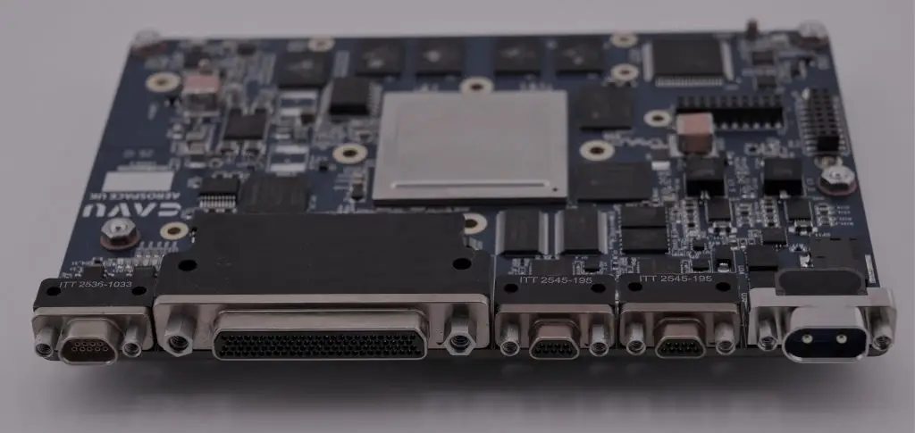
VREC-264 is an onboard computer based on Microchip PolarFire FPGA SoC. For MIL std qualification, we have bespoke connector set, input-power filtering, communication protocols and environmental compliance matrix to the target platform.
Technical specification:
Area | VREC‑264 baseline / configurable options |
Product function | Multi-input video/image acquisition, H.264 encoding, recording, timestamping, storage and data offload |
Codec | H.264 / AVC |
Chroma subsampling | 4:2:0 as standard; 4:2:2 configurable where required by the selected video path and encoder configuration |
Resolution | Up to 4K UHD, 3840 × 2160, at 30 fps |
Simultaneous streams | Up to 4 video input / recording channels in the VREC‑264 product class |
Stream architecture | Independent acquisition pipelines can be configured per input, with encoded output stored locally and/or forwarded over the selected communication interface |
Rate control | Fixed bitrate or variable bitrate |
Encoder tuning | GOP length, intra-frame interval, bitrate, latency target and quality/compression trade-off configurable per application |
Latency | Configurable; low-latency operation is available where the GOP structure, compression ratio and output interface are selected accordingly |
Image sources | Can be integrated with image sensors via standard or custom interfaces, including MIPI CSI‑2, HDMI, CameraLink, SDI, CoaXPress, LVDS, SLVS‑EC and other proprietary sensor links |
Camera heritage | Already integrated within our camera-product range with 5 MP to 50 MP sensors, including global-shutter and line-scan sensors across different frame-rate requirements |
Storage | Dual pSLC eMMC configuration, with 2 × 80 GB usable pSLC from 256 GB devices; higher capacities can be configured |
Power input | 28 V capable system configuration; additional EMI / transient filtering can be added for Teledyne FLIR’s target platform requirements |
External connectors | Current product configuration uses Micro‑D connectors; for Teledyne FLIR we can convert the external connector set to circular connectors to match installation, sealing, vibration and harnessing requirements |
Software | Linux BSP with application-level control, recording management, health monitoring and customer-specific protocol integration |
The hardware platform supports MIPI CSI‑2 and CoaXPress integration paths, and the CoaXPress IP documentation identifies support for CoaXPress v2.0 up to 12.5 Gbps. The platform also supports LVDS and related differential I/O configurations, including fail-safe LVDS features and high-speed source-synchronous interface modes.
BAYER conversion is supported through a Bayer Interpolation/debayer stage that converts raw Bayer/CFA sensor data into RGB, enabling downstream RGB-to-YCbCr formatting for the video encoder path.
Optional ISP processing can be included after Bayer conversion to refine image quality, including gamma correction and enhancement IP, plus adjustment of contrast, brightness, and colour balance.
Interfaces and protocols:
Interface class | Available options |
Video / image input | CSI‑2, HDMI, CameraLink Base / Medium / Full, SDI, CoaXPress, LVDS, SLVS‑EC, SD / composite and custom sensor interfaces |
Ethernet | Dual Gigabit Ethernet; |
Optional high speed | 10 GbE, PCIe, USB 3.0 |
Space / high-reliability links | SpaceWire, LVDS |
Control and telemetry | CAN, UART, RS‑422, RS‑485, RS‑232 |
Customer-specific protocols | MIL‑STD‑1553, ARINC‑429, AFDX or similar interfaces can be added as part of the system configuration |
Data handling | Local recording, Ethernet streaming, file-based offload and application-specific packetization |
Security features
VREC‑264 can be supplied with a system-level secure configuration intended for controlled deployment, trusted firmware updates and tamper response. The platform supports secure NVM, digital-signature services, device certificates, authenticated/encrypted storage, one-time passcode services, debug locking and zeroisation features.
At product level, we would describe the security model as:
Security function | System-level description |
Secure boot | Three-step verification: the device verifies the platform image, the platform verifies the operating image, and the operating image verifies the application package before normal operation |
Signed images | Firmware, FPGA configuration and software images can be SSL / certificate-signed so that unauthorised or modified images are rejected |
One-time programmable controls | Security configuration can be locked using one-time programmable settings to prevent unauthorised rollback, reconfiguration or debug access |
Secure update | Field updates can be accepted only when signed by an authorised key and matched to the correct device or product configuration |
Anti-tamper response | Tamper detection can trigger system lockout, secure zeroisation and device deletion / erase response depending on the configured customer policy |
Key protection | Keys and sensitive configuration data are held in protected non-volatile storage with authenticated and encrypted access modes |
Debug protection | Production units can be delivered with debug access disabled or controlled through one-time passcode access |
FIPS alignment | The system can be configured with FIPS-aligned cryptographic algorithms and evidence; formal FIPS certification scope can be agreed if required by the Teledyne FLIR programme |
Environmental position
Our recommendation is to present VREC‑264 as an ECSS-tested space-grade baseline with a tailored delta plan for DO‑160, MIL‑STD‑810H and MIL‑STD‑1275. This avoids overstating a blanket qualification while showing that the product already has relevant environmental evidence.
Requirement / standard | Current CAVU baseline evidence | Delta for Teledyne FLIR application |
EMC — ECSS‑E‑ST‑20‑07C / ECSS‑E‑HB‑20‑07A | EMC procedure covers conducted emission on power leads from 30 Hz to 100 kHz, conducted emission on power and signal leads from 100 kHz to 100 MHz, inrush current, conducted susceptibility from 30 Hz to 100 kHz, common-mode conducted susceptibility from 50 kHz to 100 MHz, short-spike transient susceptibility, magnetic-field radiated susceptibility from 30 Hz to 100 kHz, electric-field radiated susceptibility from 30 MHz to 18 GHz and radiated electric-field emission from 30 MHz to 18 GHz. | Existing EMI/EMC results can be used as the starting compliance package; for DO‑160 or MIL‑STD‑461 projects, we would map and repeat only the required sections/categories. |
Thermal vacuum — ECSS qualification profile | TVAC profile includes 10 complete operational cycles, Tmin −35 °C, Tmax +70 °C, vacuum better than 1 × 10⁻⁵ Pa, 2 h hot/cold steady-state dwell, 2 °C/min temperature transition and continuous powered health monitoring during at least 8 cycles. | This provides evidence for temperature, vacuum and thermal cycling; for airborne/ground applications, we would map it to the required DO‑160 Section 4 or MIL‑STD‑810H temperature/altitude methods. |
Sinusoidal vibration — ECSS qualification profile | Axial sine vibration is 5–30 Hz ramping from 0.625 g to 1.25 g and 30–100 Hz hold at 1.25 g; lateral sine vibration is 5–25 Hz at 0.625 g and 25–100 Hz at 1.25 g. | We would compare this against the relevant DO‑160 Section 8 category or MIL‑STD‑810H Method 514.8 profile once Teledyne FLIR confirms the platform. |
Random vibration — ECSS qualification profile | Random vibration profile is 20 Hz at 0.0088 g²/Hz, 100 Hz at 0.0088 g²/Hz, 300 Hz at 0.0200 g²/Hz, 700 Hz at 0.0200 g²/Hz, 800–925 Hz at 0.0600 g²/Hz and 2000 Hz at 0.01288 g²/Hz, with an overall level of 7.26 gRMS for 2 min/axis. | We would accept by similarity where possible or run a platform-specific delta test if Teledyne FLIR’s vibration envelope is higher or category-specific. |
DO‑160 | Not standard on the current VREC‑264 baseline. | We can prepare a DO‑160 compliance matrix once Teledyne FLIR identifies the required section categories, typically temperature/altitude, vibration, power input, RF susceptibility and emissions. |
MIL‑STD‑810H | Partially covered by existing thermal-vacuum and vibration evidence. | We can map the current evidence to relevant MIL‑STD‑810H methods; drop and salt-fog are not part of our current qualification baseline. |
MIL‑STD‑1275 | The system can operate from a 28 V supply configuration. | For vehicle power compliance, we would add the required EMI/transient filtering and validate against the selected MIL‑STD‑1275 profile. |
Connectors / harness | Current unit uses Micro‑D connectors. | For Teledyne FLIR, we can convert the external connector set to circular connectors and define pinout, shielding, backshell and grounding with the platform harness team. |
We usually prepare a short compliance cross-reference matrix for military applications. We would start from our ECSS qualification evidence, then identify the additional DO‑160, MIL‑STD‑810H, MIL‑STD‑1275 and connector/power-interface deltas required for each Teledyne FLIR target application.
To complete that matrix, we would need the target platform type, required DO‑160 categories if airborne, whether MIL‑STD‑1275 or another power-input standard applies, the required connector family, the number of simultaneous video streams including resolution and FPS, and the required chroma subsampling / latency / bitrate targets.