Typhoon Edge: Multi-Camera Intelligence for Autonomous Orbital Rendezvous and Robotic Servicing
Bringing Real-Time Vision and AI to the Spacecraft
- August 18, 2026
- CAVU Aerospace UK
Future spacecraft performing orbital rendezvous, inspection, servicing and robotic manipulation will need to operate with increasing levels of autonomy. During close-proximity operations, a spacecraft may need to process information from several cameras simultaneously, understand the relative position and orientation of another spacecraft, identify interfaces or objects, monitor a robotic arm and react to changing conditions without relying entirely on commands from the ground.
Typhoon Edge is designed to provide the onboard computing capability required for this new generation of autonomous space missions.
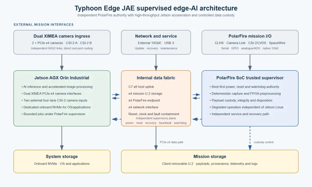
By combining the deterministic processing and flexible interfaces of a Microchip PolarFire SoC FPGA with the high-performance AI capability of an NVIDIA Jetson AGX Orin Industrial, Typhoon Edge creates a heterogeneous computing platform capable of receiving, processing and interpreting data from multiple sensors and cameras directly onboard the spacecraft.
The Jetson AGX Orin Industrial module provides up to 248 TOPS of AI performance and is specifically positioned for demanding edge AI and robotics applications, including multiple concurrent AI pipelines and high-speed sensor processing.
From Multiple Cameras to One Understanding of the Environment
An autonomous servicing spacecraft may use several cameras, each providing a different perspective of the operational environment.
For example, a mission could include:
- A long-range navigation camera for detecting and tracking the target spacecraft during approach.
- A medium-range camera for relative navigation and target pose estimation.
- Stereo or multiple cameras for depth perception and three-dimensional reconstruction.
- A robotic arm camera for monitoring the end effector and its interaction with the target.
- A wide-angle situational-awareness camera for detecting unexpected objects or changes around the servicing vehicle.
- Dedicated inspection cameras for identifying docking fixtures, grapple points, connectors, damaged structures or other mission-specific features.
Rather than treating these cameras as isolated sensors, Typhoon Edge can act as a central onboard intelligence platform, bringing multiple data streams into a common processing architecture. The result is a more complete understanding of the spacecraft’s environment.
The PolarFire SoC: Deterministic Sensor and Data Handling
The PolarFire SoC FPGA provides the deterministic and highly programmable part of the Typhoon Edge architecture. This device can be used to manage camera and sensor interfaces, handle data movement and buffering, implement mission-specific processing functions and provide deterministic processing alongside the AI subsystem. This is particularly valuable when multiple high-bandwidth data streams must be managed simultaneously.
The FPGA architecture can be configured to perform functions such as camera data acquisition and synchronization, timestamping and correlation of sensor data, image pre-processing, region-of-interest extraction, data formatting and routing, sensor fusion support, real-time hardware processing, interface conversion between different payload and camera interfaces & deterministic control functions.
By handling these functions close to the incoming data source, the FPGA can prepare and organize sensor information before it is delivered to the AI processing environment. This creates an efficient division of responsibility: the PolarFire SoC manages deterministic, interface-intensive and mission-specific processing, while the NVIDIA accelerator performs computationally intensive AI and vision tasks.
Once cameras data has been prepared and delivered to the NVIDIA Jetson AGX Orin Industrial, Typhoon Edge can execute advanced computer-vision and AI workloads. Potential onboard processing functions include object detection and classification, spacecraft recognition, relative pose estimation, tracking, optical flow analysis & robotic arm tracking.
The 248-TOPS Industrial version of Jetson AGX Orin is designed to support multiple concurrent AI application pipelines, making it particularly relevant where several sensors or cameras need to be processed at the same time.
Enabling Autonomous Orbital Rendezvous
Orbital rendezvous is a complex operation because the servicing spacecraft must continuously understand its position relative to a moving target. As the distance decreases, the type of visual information required can change significantly. At longer distances, the system may focus on detecting and tracking the target spacecraft. During the approach phase, higher-resolution camera data can be used to estimate relative position, velocity and orientation. At close range, the system may need to identify specific structural features, docking points or grapple fixtures.
Typhoon Edge can support this progression by processing multiple camera streams and combining the information into a common onboard representation of the mission environment.
- Long-range camera → Target detection and tracking
- Navigation cameras → Relative position and attitude estimation
- Stereo or multi-view cameras → Depth and 3D environment information
- Close-range cameras → Grapple point and interface recognition
- Robotic arm cameras → Manipulation monitoring and verification
This type of sensor-driven architecture aligns with the fundamental requirements of autonomous servicing systems. NASA describes autonomous real-time relative navigation as combining sensors, algorithms and processing to support safe rendezvous, alongside avionics that ingest sensor data and support rendezvous and robotic tasks.
Autonomous Robotic Arm Operations
One of the most demanding applications for multi-camera onboard intelligence is the control and monitoring of a robotic arm in orbit.
A robotic servicing mission cannot always rely on a single camera. During a manipulation operation, one camera may lose visibility because of spacecraft geometry, shadows, reflections or obstruction by the robotic arm itself. Multiple viewpoints can provide redundancy and improved situational awareness. Typhoon Edge can process information from cameras positioned around the servicing spacecraft and robotic arm to help answer critical questions:
- Where is the target object?
- What is its orientation?
- Where is the robotic end effector relative to the target?
- Is the arm approaching the correct interface?
- Has the object moved unexpectedly?
AI models running on the Jetson can identify and track relevant objects, while data from multiple cameras can be combined to improve confidence in the estimated position and orientation of the target. The resulting information can then be supplied to higher-level guidance, navigation and control software or to the robotic control system.
A Closed-Loop Onboard Intelligence Architecture
A possible Typhoon Edge processing chain could operate as follows:
Multiple Cameras and Sensors
↓
PolarFire SoC FPGA
Camera acquisition, synchronization, deterministic processing, buffering and data routing
↓
NVIDIA Jetson AGX Orin Industrial
AI inference, computer vision, object recognition, pose estimation and sensor fusion
↓
Autonomy Software
Mission logic, decision-making, trajectory assessment and robotic task planning
↓
Spacecraft GNC and Robotic Control
Thrusters, attitude control, robotic arm and end-effector commands
↓
Updated Camera and Sensor Data
This creates a continuous onboard perception-and-action loop.
During critical operations, communication delays and limited ground contact can restrict the ability of operators to control every step of a mission. Processing intelligence directly onboard allows the spacecraft to react more quickly to what its sensors observe. Typhoon Edge can therefore support a transition from a traditional architecture:
Camera → Downlink → Ground Processing → Ground Decision → Uplink Command
towards a more autonomous architecture:
Camera → Onboard Processing → AI Understanding → Autonomous Decision Support → Spacecraft Action
Ground operators can remain in the supervisory loop, defining mission boundaries, approving critical operations and receiving mission results. However, the onboard system can handle the high-rate perception and processing tasks required to understand the environment between ground contacts. This approach can also significantly reduce the amount of raw camera data that needs to be transmitted, allowing the spacecraft to downlink mission-relevant information, selected imagery, detected events or processed results instead of continuously transmitting every sensor stream.
Mission Applications
The Typhoon Edge architecture can support a wide range of future autonomous space missions, including:
- Orbital Rendezvous and Proximity Operations- Multi-camera tracking and AI-based understanding of the target spacecraft during approach and close-proximity operations.
- On-Orbit Servicing- Identification of service interfaces, inspection of spacecraft structures and support for robotic servicing operations.
- Robotic Capture- Tracking a target object and supporting autonomous or semi-autonomous robotic arm operations.
- Space Debris Interaction- Visual detection, tracking and characterization of objects before capture or removal operations.
- Satellite Inspection- AI-assisted detection of structural anomalies, damage or changes in spacecraft configuration.
- In-Orbit Assembly- Multi-camera monitoring and AI-assisted verification of robotic assembly operations.
- Autonomous Docking- Real-time perception and pose estimation to support docking and capture sequences.
Typhoon Edge is designed to help move that intelligence onboard—transforming multiple streams of sensor data into real-time awareness and enabling a new generation of autonomous spacecraft operations. This is possible only with extended external interfaces listed below:
External interface
Interface | Released configuration | Rate / electrical form | Connector |
camera PCIe | Several independent PCIe x4 camera links | PCIe Gen2 x4 per camera; 16 Gb/s effective link data rate; common clock, reset, protected 12 V and camera I/O | JX01, JX16 |
Jetson CSI-2 | 2 × independent four-data-lane inputs | MIPI D-PHY; clock + 4 data pairs; up to 2.5 Gb/s per data lane | JC18, JC17 |
PolarFire camera | 1 × four-lane CSI-2 plus auxiliary LVDS/GPIO | Camera-compatible QSH interface; camera USB contacts unused; no camera power | JC04 |
Camera Link HS | 4 full-duplex copper X-protocol lanes | Up to 10.3125 Gb/s per SerDes lane | JC05 |
Camera Link | Base plus Medium/Full extension | SDR-26; up to 85 MHz Camera Link clock; non-PoCL | JC11, JC12 |
High-rate Ethernet | 1 × external 10GbE | 10 Gb/s copper | JE15 |
PolarFire Ethernet | 1 × native PolarFire SoC 1GbE | Transformer-less, capacitively coupled 1000BASE-T; auto-negotiation and Auto-MDIX | JE13 |
SpaceWire | 2 × independent links | ECSS-E-ST-50-12C; 2 to 200 Mb/s per link | JW02, JW03 |
USB | 1 × operational USB 3 host; 1 × Jetson recovery USB-C | USB 3 at 5 Gb/s plus USB 2 fallback; protected 5 V VBUS on JU07 | JU07, JS09 |
Serial / digital I/O | 4 × CAN, 4 × RS-422, 4 × RS-485, 4 × RS-232, I²C, 32 buffered GPIO and 8 direct I/O | CAN to 1 Mb/s; RS-422/485 to 16 Mb/s; RS-232 to 921.6 kb/s; I²C to 400 kHz | JD10 |
Analogue / ADV | 16-channel simultaneous acquisition | 16-bit; ±5 V or ±10 V; up to 1 MSPS per channel-pair; 2× to 128× oversampling | JA14 |
PolarFire service | JTAG, USB 2.0 and dual debug UART | Service-only; capped during flight | JS08 |
Power | 12 V DC nominal, two-contact input | 12 V to 18 V DC continuous | JP06 |
The PolarFire-side computer retains the released OBC-HYPER-POLAR memory, serial-bus, GPIO, analogue-acquisition and service architecture. Typhoon Edge presents one native PolarFire SoC Gigabit Ethernet interface and two independent SpaceWire interfaces.
The following register identifies every customer-accessible equipment connector. The second character identifies function: JX for PCIe, JU for USB, JE for Ethernet, JW for SpaceWire, JC for camera, JP for power, JD for digital I/O, JA for analogue and JS for service. Numeric suffixes run continuously in physical position order: Mission Face 1 upper row after JX01, Mission Face 1 lower row, Mission Face 2 upper row, then Mission Face 2 lower row. JS08 and JS09 remain capped during flight.
Ref | Function | Board destination | Equipment connector | Mating harness connector / backshell | Access |
JX01 | XIMEA camera A, PCIe x4 | Interface board / Jetson C5 | FI-RE51S-HF-R1500 | XIMEA CBL-MX-X4G2-0M40 or qualified FI-R 51-position cable | Flight |
JW02 | SpaceWire A | PolarFire SoC board | M83513/12-H01CP | M83513/04-H03N | Flight |
JW03 | SpaceWire B | PolarFire SoC board | M83513/12-H01CP | M83513/04-H03N | Flight |
JC04 | PolarFire camera CSI-2 / auxiliary LVDS | PolarFire SoC board | QSH-020-01-L-D-DP-A | QTH-020-01-L-D-DP-RA or qualified HQDP assembly | Flight |
JC05 | Camera Link HS, copper | PolarFire SoC SerDes | GMMD-HR8T-2UM-474C | Qualified GMMD 8-twinax cable assembly, key C | Flight |
JP06 | 12 V DC input | PolarFire SoC power entry | GMPM2-B112R-CBRT-SU | GMPM2-B112P + GMPMBT2-B-EM | Flight |
JU07 | General USB 3 | Interface board / Jetson USB | GMMD-HR2T9-2UM | Qualified GMMD cable assembly, matching key | Flight |
JS08 | PolarFire service: JTAG, USB, debug UART | PolarFire SoC board | MDM-15PH003B | MDM-15SH003K + MDM-BT-15TE-SJS | Service |
JS09 | Jetson update and recovery USB-C | Interface board / Jetson recovery USB | MUSBR-M1C1-M0 | Retained USB Type-C service cable | Service |
JD10 | Serial, I2C and 3.3 V GPIO | PolarFire SoC board | MDM-100PCBRP-A174 | MDM-100SH003K-A174 | Flight |
JC11 | Camera Link Base | PolarFire SoC board | 12226-8250-00FR | 3M 1Sx26 Camera Link SDR cable assembly | Flight |
JC12 | Camera Link Medium/Full | PolarFire SoC board | 12226-8250-00FR | 3M 1Sx26 Camera Link SDR cable assembly | Flight |
JE13 | PolarFire SoC native 1GbE | PolarFire SoC board | MDM-9PCBRP | MDM-9SH003K | Flight |
JA14 | Analogue / ADV | PolarFire SoC board | MDM-25PH003K | MDM-25SH003M7 | Flight |
JE15 | External copper 10GbE | Interface board / network interface | GMMD-HR4T-2UM | Qualified GMMD 4-twinax cable assembly | Flight |
JX16 | XIMEA camera B, PCIe x4 | Interface board / Jetson C4 | FI-RE51S-HF-R1500 | XIMEA CBL-MX-X4G2-0M40 or qualified FI-R 51-position cable | Flight |
JC17 | Jetson CSI-2 B, four lanes | Interface board / Jetson | GMMD-HR5T9-2UM-474B | Qualified GMMD 5T9 cable assembly, key B | Flight |
JC18 | Jetson CSI-2 A, four lanes | Interface board / Jetson | GMMD-HR5T9-2UM-474A | Qualified GMMD 5T9 cable assembly, key A | Flight |
Interface descriptions
Camera PCIe interfaces — JX01 and JX16
JX01 and JX16 are independent 51-position JAE camera interfaces for several cameras. JX01 routes Camera A to Jetson controller C5 operated in x4 mode; JX16 routes Camera B to controller C4 in x4 mode. This is the AGX Orin-specific controller assignment and differs from the Xavier NX carrier mapping used elsewhere in the product family. Each connector follows the XIMEA X4G2 contact assignment and carries four camera-transmit pairs, four camera-receive pairs, the 100 MHz common reference clock, active-low reset, protected 12 V camera power, isolated trigger I/O and four non-isolated bidirectional I/O lines.
Jetson camera interfaces — JC18 and JC17
JC18 and JC17 each provide an independent four-lane MIPI CSI-2 camera input. Five matched twinax pairs carry one clock and four data lanes. Nine discrete contacts carry I2C control, active-low reset, active-low power-down, frame synchronization, presence, signal return and two reserved contacts. Camera power is not supplied at either connector.
PolarFire camera interface — JC04
JC04 is the camera-side-compatible Samtec QSH interface for the CAVU sLDU-345 family. It carries four CSI-2 data lanes, CSI clock, released auxiliary LVDS pairs, I²C and camera GPIO. Contact 26 is the 24 MHz nominal camera reference-clock monitor input. Contact 28 is the active-high camera power-down command. The camera USB contacts are deliberately not used and remain unconnected.
Camera Link HS — JC05
JC05 carries four full-duplex copper Camera Link HS X-protocol lanes directly to the PolarFire SoC SerDes fabric. Eight matched twinax pairs provide four camera-to-host and four host-to-camera lanes; command and control transactions use the Camera Link HS protocol.
Camera Link — JC11 and JC12
JC11 provides the Camera Link Base cable interface. JC12 provides the additional channels used for Medium and Full configurations. Standard SDR-26 Camera Link cable assemblies are used. Camera control serial and trigger functions remain on the assigned standard contacts. The interfaces are non-PoCL; camera power is not supplied.
Ethernet — JE13 and JE15
JE13 is the native PolarFire SoC 1000BASE-T interface on Micro-D9. JE15 is the external 10GbE copper mission interface. JE15 carries four matched copper data pairs and does not supply remote power.
SpaceWire — JW02 and JW03
JW02 and JW03 are independent SpaceWire links presented on two side-by-side Micro-D9 connectors on Mission Face 1. Each interface includes Data/Strobe transmit and receive pairs plus signal return and operates from 2 Mb/s to 200 Mb/s.
General USB 3 — JU07
JU07 provides one rugged general-purpose USB 3 interface with SuperSpeed transmit/receive pairs, USB 2 D+/D− and ground. It is the only operational general USB port.
Serial, I²C and GPIO — JD10
JD10 preserves the released OBC-HYPER-POLAR 100-contact interface assignment. It provides differential serial channels, I²C, 3.3 V direct I/O, protected outputs, returns and reserved contacts. NC contacts shall not be wired.
Analogue / ADV — JA14
JA14 preserves the released 25-contact analogue/ADV interface, including analogue inputs, analogue returns, reference and control contacts. Apply only signals within the released input range and maintain separation from high-current power conductors.
Service interfaces — JS09 and JS08
JS09 is the rugged Jetson USB-C update/recovery port. JS08 contains PolarFire JTAG, USB and debug UART. Both are on the lower row of Mission Face 1, with JS08 between JU07 and JS09. These connectors are capped during flight and are opened only under an authorised service or integration procedure.
Internal removable U.2 storage
The baseline mission store is a 1.92 TB, 2.5-inch, 15 mm U.2 NVMe device using SFF-8639 and a dedicated PCIe x4 path. The retained screwed lid permits client replacement without disturbing external harnesses. The unit shall be powered off, discharged and ESD-controlled before the lid is opened.
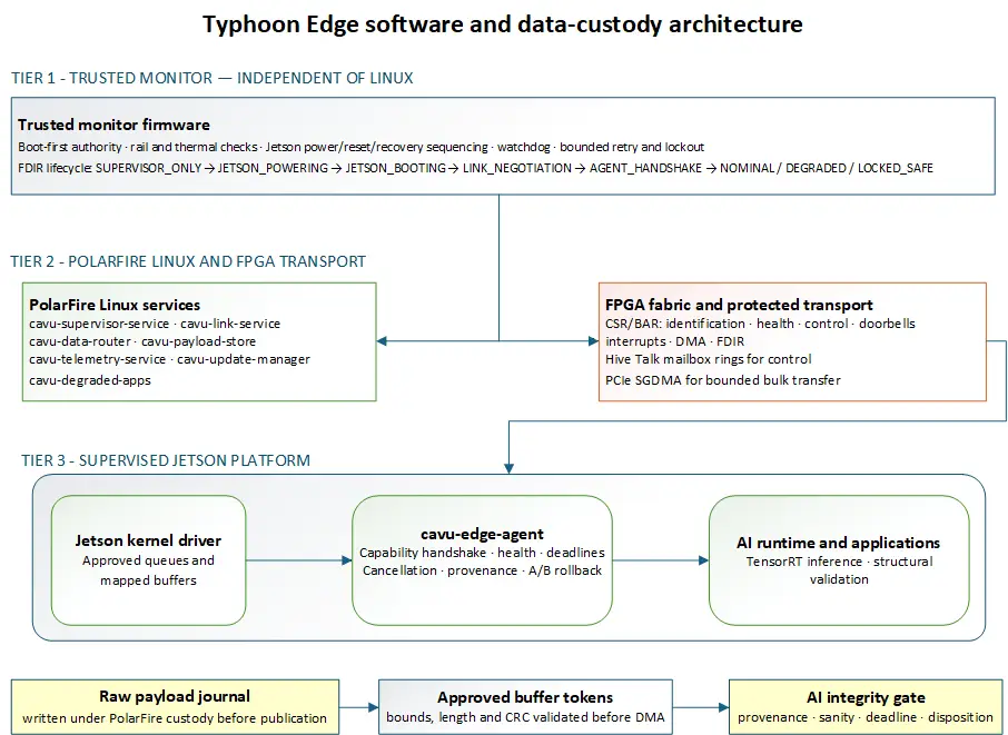
Trusted monitor, PolarFire services, FPGA transport and supervised Jetson application stack