
TCU Heater Control Architecture and PWM Power Balancing Strategy
- October 16, 2026
- CAVU Aerospace UK
The Thermal Control Unit (TCU) is a subsystem designed to regulate the temperature of critical spacecraft components through the use of resistive heaters. It is equipped with 48 heater output channels, among which up to 32 channels are actively assigned for operational use in a given mission scenario. The heaters are controlled through pulse-width modulation (PWM) signals sourced from the TCU’s FPGA-based controller, providing fine-grained and energy-efficient thermal control.
Mission Specific Heater Specifications
The users usually provide a detailed spreadsheet containing specifications for each heater. These include:
- Heater ID and function (e.g., PROP, CPLATE, etc.)
- Resistance value (Ω) per heater
- Nominal power rating (W)
- Target power to be delivered (W)
- The specific TCU channel to which each heater is mapped
These specifications form the baseline inputs to the control system. The power setpoints vary per heater based on mission thermal requirements, and resistances range from as low as ~39 Ω to over 119 Ω.
The primary goal of the TCU firmware is to:
- Deliver precise power levels to each heater according to the client’s spreadsheet.
- Avoid power supply spikes and ensure reliable operation by optimizing switching across the PWM cycle.
- Support real-time monitoring of current and power delivered to each heater.
- Ensure compact and power-efficient control architecture that can scale with the number of heaters while staying within spacecraft SWaP (size, weight, and power) constraints.
The current implementation achieves this through PWM-based voltage control and a phase-distributed activation scheme, ensuring both accuracy and safety. The design is rigorously verified using a dedicated tester module, which emulates the exact heater resistances provided in the client’s specification and serves as a benchmark for hardware validation.
The Challenge of PWM Implementation
Why PWM Instead of DC Voltage Control?
Delivering specific power to 32 independent resistive heaters may, in principle, be achieved via direct DC voltage regulation. However, such an approach would require 32 independent DC-DC converters—one per heater channel. This would introduce substantial challenges:
- Massive inefficiency due to individual power regulation circuits.
- Excessive physical footprint on the PCB and within the enclosure.
- Thermal dissipation complexity from having dozens of heat-generating regulators.
- Increased system complexity, BOM cost, and risk of failure due to multiple active regulation paths.
Instead, the TCU uses a centralized 28V power bus with PWM-based high-side MOSFET switching per channel. Each heater is driven by modulating its ON-time within a fixed-frequency PWM cycle (10 kHz), thereby adjusting its average delivered power while switching between full 28V and OFF states. This method achieves:
- High efficiency (MOSFETs dissipate minimal power when fully ON or OFF)
- Compactness
- Reduced complexity
- Fast response and digital controllability
The Tester Module: Validation via Real Resistive Loads
A critical part of verifying the TCU performance is the tester module, a hardware unit built with the exact resistance values provided by the client. Each tester channel emulates the resistive load of one heater, and is used to:
- Validate that the PWM drive circuits function correctly under real resistive load.
- Measure power output and current behavior against expected profiles.
This tester module is the ground truth reference for validating that each channel delivers the requested power safely and accurately.
Measuring Power: The Challenge of Pulsed Currents
PWM switching introduces pulsed current waveforms:
- Each heater receives sharp ON/OFF transitions.
- The current waveform is non-continuous and repetitive, mimicking a square wave rather than a steady-state DC signal.
- This behavior poses significant challenges in accurately measuring power.
- Problem with Peak Measurement:
- If current is sampled at its peak, the calculated power would be overestimated.
If sampled when PWM is OFF, the measured current is zero, leading to a false indication of no power.
RMS Filtering Solution
To resolve this, a low-pass filter is used in the measurement path:
- It smooths the pulsed current into a near-RMS equivalent voltage signal.
- This allows the TCU to sample and calculate power more accurately over time.
- The filter response is tuned to match the 10 kHz PWM frequency, ensuring balance between ripple rejection and latency.
However, due to the filter order, there is a small delay (phase lag) between actual heater switching and observed voltage.
The resulting waveform is slightly smoothed, which is acceptable for average power estimation but must be accounted for in time-sensitive control loops
External Power Supply Observation
Power observed from the input power supply terminals (e.g., a 28V bench supply) will also show pulsed behavior, not true RMS power. Users monitoring the supply current should:
- understand that instantaneous readings reflect dynamic PWM effects.
- Use averaging tools or oscilloscope integration features if accurate system-wide power consumption is needed.
The Implemented Spread-Spectrum PWM System
The Thermal Control Unit is equipped with 48 high-side heater driver outputs, of which 32 channels are actively used in the current mission profile. Each heater must receive a programmable power level depending on its thermal control objective. The most efficient way to deliver this power is through pulse-width modulation (PWM), using a shared 28 V DC supply.
However, using PWM on multiple channels simultaneously creates a significant challenge. If the ON phases of multiple PWM signals overlap—especially during the rising edge of the PWM cycle—the instantaneous current demand on the 28 V supply can spike dramatically, well beyond the average current calculated from steady-state duty cycles. This scenario can:
- Exceed power supply limits.
- Trigger overcurrent protection.
- Induce voltage ripple or EMI issues.
Cause unpredictable system behavior or mission interruption
Worst-Case Load Aggregation
The client’s provided heater specification spreadsheet defines heaters with varying resistances and required power levels. For the active 32-channel setup, the configuration includes:
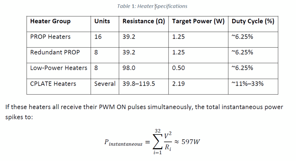
In contrast, the total average power is only ~65 W. The discrepancy highlights the danger of uncoordinated PWM activation, where safe average loads can still cause dangerous peak loads if mismanaged.
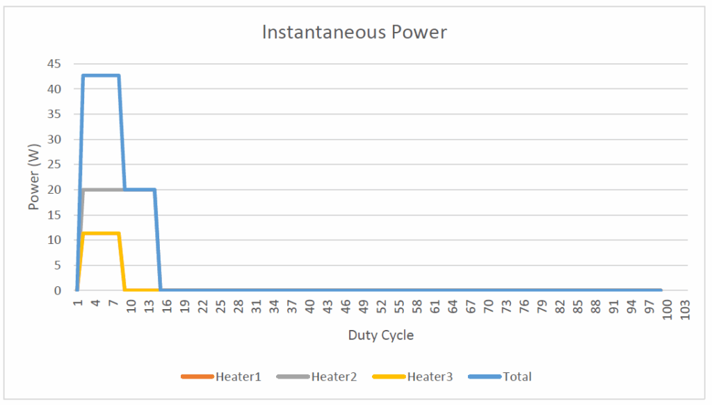
Example of Total Power Consumption for 3 Heaters with Overlapping ON Cycle
Phase-Distributed PWM: The Solution
To mitigate this, the TCU implements a spread-spectrum phase-distributed PWM algorithm. The idea is to assign unique phase offsets to each PWM signal so that no two heaters turn ON at the exact same moment. This spreads the current draw evenly across the 100 μs PWM period (10 kHz), dramatically reducing peak power draw.
Key Parameters:
- PWM Frequency: 10 kHz (period = 100 μs)
- Phase Resolution: Calculated dynamically to divide ON pulses across time
- Wrap-Around Handling: Heaters with long ON durations (e.g., 33%) are wrapped across the cycle end
Implementation Mechanics
Duty Cycle Computation
For each heater:

Phase Offset Assignment
The ON phase start of each channel is spaced to avoid concurrent switching. A linear spacing model is used:

Pulse Overlap Handling
If ∅𝑖+𝑇𝑜𝑛,𝑖>𝑇𝑃𝑊𝑀, the pulse wraps around to the next cycle. Firmware logic ensures:
- Correct PWM high duration
- No truncation or overlap
- Accuracy of average delivered power
3.5. Power Simulation Results
A simulation was run to verify the system’s power stability:
- All 32 heaters were activated with their respective duty cycles.
- Phase-distributed PWM control was applied.
- Instantaneous power was calculated at 1 μs resolution.
Results:
- Max instantaneous power reduced from ~597 W (uncoordinated) to <140 W.
- The power curve was smoothed, with no sharp peaks.
- Average power matched target values exactly.
- Phase spacing successfully flattened the power draw profile across each 100 μs PWM cycle.
Firmware Architecture
- PWM Generation: Timer-based PWM channels with programmable phase offsets.
- Duty Update: Real-time configurable via command interface.
- Phase Register Bank: Updated during configuration or system reset.
- Double-Buffering: Ensures glitch-free updates mid-operation.
Benefits of This System
- Maintains heater precision across different thermal demands.
- Prevents supply overload even in worst-case 32-heater scenarios.
- No additional hardware needed (e.g., DC-DC converters).
- Software-controlled and reconfigurable for new missions.
Summary of Impacted Modules
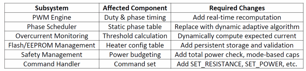
The current TCU design implements a robust, high-efficiency heater control system that operates up to 32 active heater channels using a centralized 28 V PWM-based switching scheme. A key innovation in the design is the spread-spectrum phase-distributed PWM algorithm, which ensures that:
- Heaters do not switch on simultaneously, and
- The system never exceeds the defined power envelope (40–50 W maximum average, <140 W instantaneous peak even in stress-tested simulation).
This approach is based on a set of predefined heater parameters, including resistance and target power values, and is tightly coupled with a static scheduling mechanism to maintain deterministic behavior.
Dynamic Configuration Risks
The request to allow run-time configurability of heater resistance and power values significantly alters the assumptions on which the control firmware was architected. As analyzed in Chapter 4, this introduces several layers of complexity and risk:
- Recalculation of duty cycles
- Risk of overlapping ON pulses and resulting overcurrent
- Violation of system-wide power limits
- Fault misdetection due to variable current profiles
- Non-deterministic startup behavior
- Increased software validation burden
- Loss of mission assurance guarantees without exhaustive verification of every possible configuration
Real-World Consideration: Redundancy and Activation Profiles
While the simulation and worst-case calculations assumed all 32 heater channels might be active concurrently, it is important to clarify that:
- Several of the 32 heaters are explicitly designated as redundant, particularly among the PROP and CPLATE groups.
- Redundant heaters are not expected to be active at the same time as their primary counterparts under normal mission scenarios.
- This means the true maximum number of simultaneously active heaters is likely much lower—possibly around 16 to 24 in practice.
- Nevertheless, to ensure robustness under all conditions, including failure or redundancy-switching scenarios, the system is engineered against the absolute worst case: 32 channels ON with independent duty cycles and power settings.
- Allowing the heater configuration to change dynamically would break this guarantee and expose the system to unexpected overlaps in worst-case activation states.
The TCU heater control architecture has been engineered for high reliability, deterministic performance, and safe operation under tight power constraints. Allowing dynamic heater parameters without a full system re-architecture would compromise the integrity of the phase-distributed PWM model, the stability of the power system, and the traceability required for space-grade qualification.
We encourage the client to treat this as a one-time configuration activity to be resolved in collaboration. Once finalized, we will deliver a firmware patch with all parameters safely integrated, fully tested, and validated against the mission profile.