
TCU Heater Channel Current Limits, Connector Contact Heating and PWM Input Current Scheduling
- July 14, 2026
- CAVU Aerospace UK
1 Per-Channel Current Limit and PWM ON-State Current
The per-channel current limit should be considered before PWM averaging, meaning it is based on the heater current during the PWM ON time, not only the average current after PWM is applied. For a resistive heater, the ON-state current is defined by the heater resistance and the applied voltage:
I_ON = V_HEATER / R_HEATER
So, if a heater has low resistance and draws 5–7 A when fully ON, the connector, harness, MOSFET path and current-sense path will see that 5–7 A pulse current during the PWM ON interval. PWM reduces the average delivered power, but it does not reduce the instantaneous current during the ON part of the cycle.
For example:
36 V input with a 10 Ω heater:
I_ON = 36 V / 10 Ω = 3.6 A
This is below the 5 A per-channel contact level. However, if the heater resistance were lower, for example:
36 V input with a 6 Ω heater:
I_ON = 36 V / 6 Ω = 6 A
then the channel would see 6 A during each PWM ON pulse, even if the PWM duty cycle reduces the average current to 3 A. Therefore, we should check both the heater resistance and the PWM duty cycle when defining the operating point.
2 Connector Contact Heating at 5 A Continuous
For the heater channels, the practical heating limit on the driver side is mainly related to the connector contacts and harness interface. The internal PCB current paths and MOSFET stages have significant margin and are designed for much higher current capability, up to approximately 20 A in the relevant paths.
Therefore, when we discuss the 3 A or 5 A heater-channel configuration, the main item being checked is the connector/contact thermal loading, not the PCB or MOSFET limitation.
The connector contacts are metallic, typically copper/brass alloy with suitable plating, and the contact resistance is approximately:
R_contact ≈ 10 mΩ per contact
Each heater channel uses one positive contact and one return contact. At 5 A continuous current, the voltage drop and contact dissipation are:
Voltage drop per contact = I × R = 5 A × 10 mΩ = 50 mV
Power per contact = I² × R = 5² × 0.01 = 0.25 W
Power per heater pair = 0.25 W + 0.25 W = 0.5 W
So, at 5 A, each heater channel produces approximately 0.5 W total contact dissipation, shared between the positive and return contacts. This is a connector/contact thermal calculation, not a PCB or MOSFET limitation.
Each heater connector serves 12 heater channels, with 12 positive contacts and 12 return contacts. Therefore, for a fully populated 12-heater connector at 5 A per channel:
Per channel contact dissipation = 0.5 W
12 channels × 0.5 W = 6 W total connector contact dissipation
Equivalent view:
24 contacts × 0.25 W/contact = 6 W
This dissipation is distributed across the connector contact set, not concentrated in a single pin.
3 PWM Contact Heating on an RMS Basis
The PWM case is slightly different because the connector contact heating follows RMS current, not only arithmetic average current:
I_AVG = I_ON × duty cycle
I_RMS = I_ON × √duty cycle
P_contact = I_RMS² × R_contact
Example:
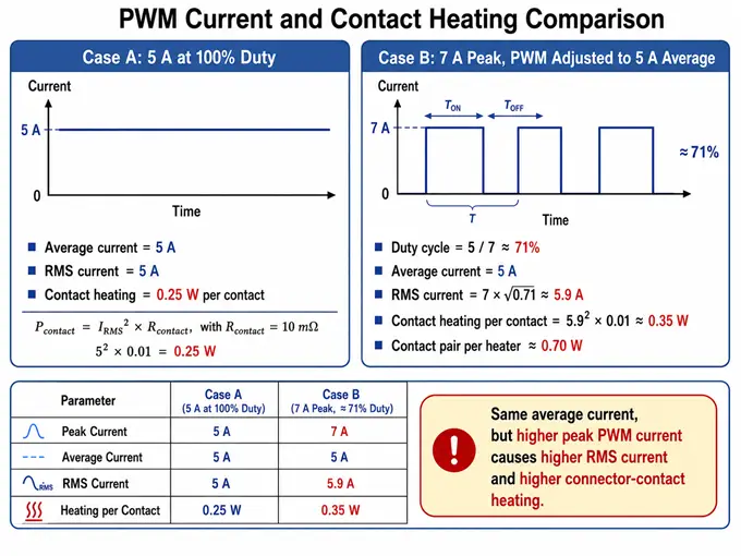
So, when we define a 5 A heater-channel configuration, we treat this as an ON-state / RMS current configuration, not only a PWM-average value. This gives the correct basis for connector contact heating.
4 System-Level Input-Current Management
The connector-level current also needs to be considered together with the total accumulated system input current. The maximum current capability is therefore based on both:
1) Heater output connector/contact rating
2) Power input connector/system input-current rating
The individual heater channels may be able to serve more current electrically, but the system-level input current is managed by firmware.
In the current configuration, the continuous accumulated input current should be kept within:
Continuous-equivalent input-current cap = 25 A
We can also allow a higher short-duration instantaneous input current:
Allowed instantaneous input-current cap = 35 A
This means 25 A is the continuous-equivalent input-current cap, while 35 A is an allowed instantaneous ceiling during PWM phase scheduling. The firmware does not treat 35 A as a continuous operating point.
At system level:
I_TOTAL_AVG = Σ(I_ON_channel × duty_channel)
I_TOTAL_INSTANTANEOUS(t) = sum of all heater currents that are ON at that moment
The control rule is:
I_TOTAL_AVG ≤ 25 A
I_TOTAL_INSTANTANEOUS ≤ 35 A
5 Phase-Distributed PWM Strategy
To control instantaneous current, the TCU uses a phase-distributed PWM strategy. Instead of switching all heater channels ON at the same point in the PWM cycle, the firmware assigns phase offsets to distribute heater ON times across the 10 kHz / 100 µs PWM period.
Conceptually:
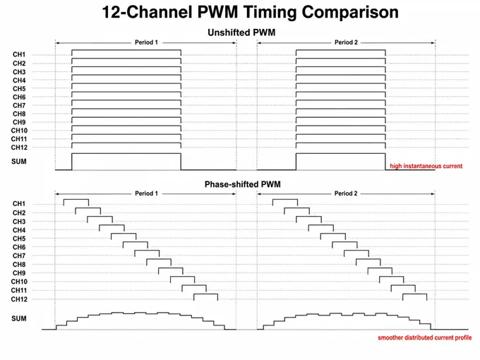
This phase-shift mechanism is already implemented in the TCU firmware. It distributes the PWM activation across the 100 µs PWM cycle and smooths the total input-current profile.
6 Heater ON-State Currents at 36 V Input
For example, at 36 V input, the heater ON-state currents are:
|
Heater resistance |
ON-state current per channel |
ON-state power per channel |
|
10 Ω |
3.60 A |
129.6 W |
|
25 Ω |
1.44 A |
51.8 W |
|
50 Ω |
0.72 A |
25.9 W |
|
75 Ω |
0.48 A |
17.3 W |
All of these are below the 5 A per-channel output-contact level, so the individual heater outputs remain inside the channel-current envelope. The main control point then becomes the accumulated input current.
7 Representative 48-Output Scenario Analysis
For the representative 48-output configuration, using the repeating pattern:
|
CH1–CH6 = 10 Ω |
CH25–CH30 = 10 Ω |
|
CH7–CH12 = 25 Ω |
CH31–CH36 = 25 Ω |
|
CH13–CH18 = 50 Ω |
CH37–CH42 = 50 Ω |
|
CH19–CH24 = 75 Ω |
CH43–CH48 = 75 Ω |
Four representative scenarios that cover the main operating cases:
|
# |
Description |
Average input current |
35 A duration per 100 µs PWM period |
Remainder current |
RMS over PWM period |
|
1 |
All 48 outputs active, balanced duty |
24.99 A |
30 µs |
20.71 A |
25.84 A |
|
2 |
Low-resistance / high-current outputs dominant |
24.98 A |
25 µs |
21.67 A |
25.66 A |
|
3 |
High-resistance / many-output case |
25.01 A |
40 µs |
18.33 A |
26.30 A |
|
4 |
Connector-localised high-current case |
24.99 A |
35 µs |
19.62 A |
26.05 A |
This gives the system additional instantaneous heater-driving flexibility while maintaining the continuous-equivalent input-current cap.
8 Operating-Point Summary and Configuration Guidance
So, the practical interpretation is:
Heater Outputs:
3 A/channel: Standard conservative configuration.
5 A/channel: Configured upper safe level for the existing connector/harness concept.
7 A/channel: Available high-current configuration. Supported on selected heater channels, provided the harness allocation, connector contact dissipation, RMS current, and accumulated input-current limits remain within the configured operating envelope. The TCU manages the total input current through PWM duty cycle, phase distribution, and heater sequencing.
Main Power Input:
25 A input current: Continuous-equivalent accumulated input-current cap.
35 A input current: Allowed instantaneous cap during phase-distributed PWM scheduling.