
Radiation Performance of RT OBC-HYPER-POLAR
Radiation-Tolerant Product Configuration — COTS, Tier 0 - 4
- August 22, 2026
- CAVU Aerospace UK
Abstract
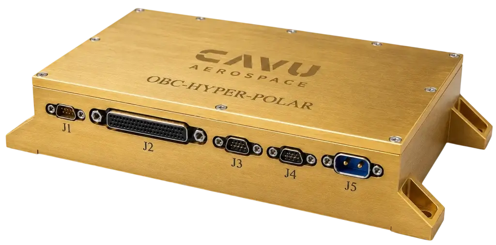
OBC-HYPER-POLAR RT is the radiation-tolerant product family of the HYPER-POLAR onboard computer. The common platform combines the Microchip PolarFire SoC compute architecture, 4 GB MSS main memory, 8 GB fabric memory, redundant boot storage, high-capacity mass storage and a broad set of serials, SpaceWire, analogue and Gigabit Ethernet interfaces. Baseline and Tiers 0–4 provide cumulative radiation-performance configurations while preserving the common mechanical, software and interface architecture.
The product family provides a cumulative radiation-performance progression. Tiers 0–3 retain MPFS460T and progressively harden power, communications, boot, memory, analogue and Ethernet domains. Tier 4 uses RTPFS460ZT and provides the maximum-RT compute configuration with nonvolatile configuration immunity. Memory and high-capacity storage are independently protected fault domains, with their published device-specific SEE limits stated explicitly.
Tier 2 uses radiation-tolerant DDR4 for the 4 GB MSS main-memory function. The PolarFire SoC MSS supports 16/32 data I/Os and 18/36 data I/Os with ECC; the HYPER-POLAR RT MSS configuration uses 32 data I/Os plus 4 ECC I/Os, forming a 36-bit SECDED interface. The selected 72-bit RT DDR4 memory module has a defined 2:1 width relationship to the 36-bit MSS interface, while 64/72-bit memory operation remains on the fabric DDR controller.
HYPER-POLAR RT separates boot and critical state from bulk mission-data storage. Dual radiation-hardened QSPI NOR devices and SPI MRAM/FRAM carry boot, recovery metadata and critical state. The 512 GB baseline mass-storage domain is independently protected and recoverable. Space eMMC and fabric-attached RTIMS/NAND configurations provide radiation-tolerant storage variants with their published TID/SEE limits and capacity boundaries stated in Tier 3.
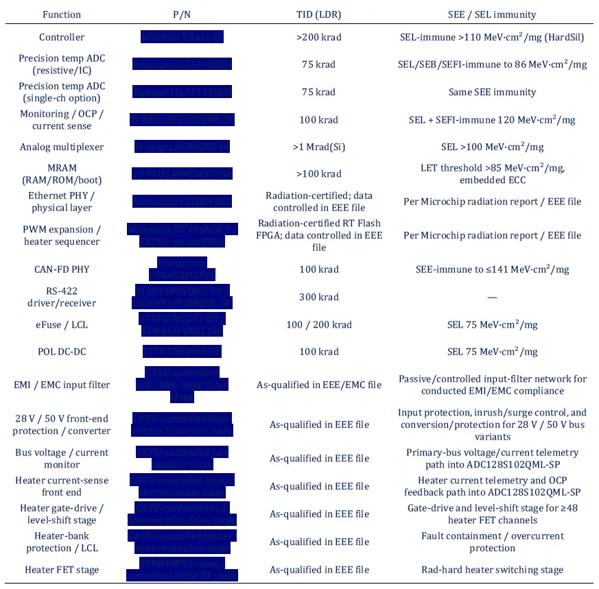
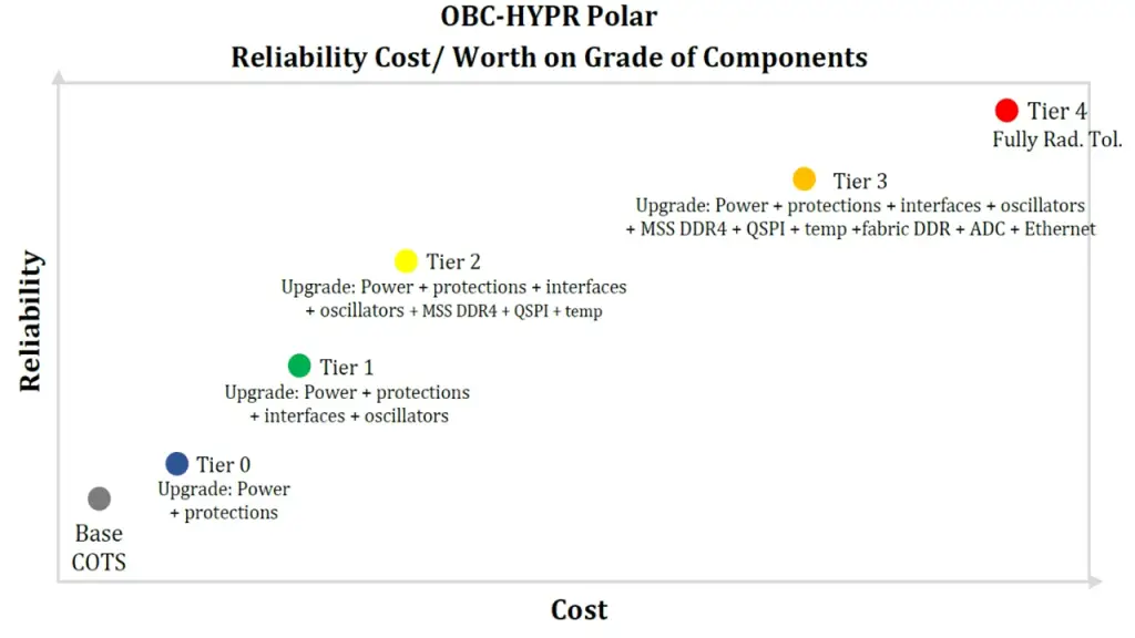
Functional radiation coverage of the cumulative OBC-HYPER-POLAR RT product tiers.
Tier performance is stated by the functional domains hardened, the manufacturer-published component data and the fault-containment mechanisms provided by the product. Box-level TID values are used only where supported by the applicable component set, shielding basis and qualification evidence.
Product Baseline and Radiation-Relevant Architecture
Compute and memory topology
Domain | HYPER-POLAR baseline | Radiation performance implementation |
Compute | MPFS460T PolarFire SoC | Commercial/terrestrial PolarFire SoC; not treated as an RHA component in Tiers 0–3. |
MSS main memory | 4 GB LPDDR4 | Tier 2 uses 4 GB radiation-tolerant DDR4 on the 36-bit MSS SECDED interface. |
Fabric memory | 8 GB DDR4 | Tier 3 uses radiation-tolerant DDR4 with fabric ECC/EDAC, scrubbing and independent fault-domain recovery. |
Boot | 2× 256 Mbit or 2× 512 Mbit QSPI NOR | Dual-device architecture supports primary/fallback. 512 Mbit rad-hard QSPI NOR is available. |
Bulk storage | 2× 256 GB eMMC | Bulk storage is a separately protected and recoverable fault domain; space eMMC and fabric-attached RTIMS/NAND configurations are documented in Tier 3. |
Nonvolatile auxiliary | SPI MRAM and SPI FRAM | Suitable for configuration, state checkpoints, critical metadata and event logs; can be isolated from bulk-storage risk. |
External interfaces and fault domains
Interface | Qty | Tier | Radiation performance implementation |
CAN | 4 | Tier 1 | MPFS MSS provides two hard CAN controllers; remaining CAN capability is implemented through fabric-side logic/IP. All four external PHYs are upgraded. |
RS-422 | 4 | Tier 1 | Use QML/RHA line drivers/receivers; reset/retry at protocol layer. |
RS-485 | 4 | Tier 1 | Use space transceivers supporting EIA-485/422 as appropriate; keep each bus electrically fault-contained. |
SpaceWire | 1 | Tier 1 | External LVDS transceiver set upgraded; selected two-driver/two-receiver space device or QML LVDS pair. |
1 Gb Ethernet | 2 | Tier 3 | Two radiation-tolerant GbE PHYs; link state, SEFI monitoring and reinitialization included in FDIR. |
PolarFire architectural attributes relevant to radiation
- PolarFire uses nonvolatile SONOS configuration technology, avoiding the continuous configuration-scrubbing burden characteristic of SRAM-configured FPGAs. Microchip markets the RT family specifically around zero configuration upsets.
- The MSS includes ECC-protected cache/LIM resources and a dedicated external DDR controller. External volatile memory remains a radiation-sensitive system element even when the FPGA configuration itself is robust.
- Fabric logic supports EDAC, memory scrubbing, watchdogs, redundant state machines, interface controllers and fabric-hosted NAND/RTIMS storage control. TMR is applied to protected control logic where required by the RT configuration.
- Power-domain partitioning allows destructive events or persistent SEFIs in external memories/PHYs to be current-limited and recovered by controlled power cycling.
Radiation Performance Criteria and Evidence Basis
Parameter | CAVU OBC radiation criterion | Use in this report |
Box-level TID product target | 100 krad (Si) | Target for the maximum-RT configuration; mission dose-depth/RDM closure uses the applicable environment and shielding analysis. |
Primary component TID criterion | ≥75 krad (Si), preferably LDR/RHA evidence | Below-criterion parts are stated as controlled performance boundaries with the applicable containment mechanism. |
Destructive SEE / SEL criterion | Latch-up immune or LET ≥75 MeV·cm²/mg | Below-criterion high-density memories/storage are power-contained, recoverable and explicitly identified in Annex B. |
Configuration upsets | No mission-critical loss of configuration | RT PolarFire nonvolatile configuration is a major architectural advantage. |
Recoverable SEE | Detect, correct, retry or power-cycle | ECC/EDAC, scrubbing, watchdogs, protected islands, redundant boot and protocol retry. |
Evidence | Primary manufacturer evidence | Official data sheets, radiation reports, QML/RHA product guides and vendor product pages. |
Evidence grades used in the component tables: A = QML/RHA or dedicated manufacturer radiation report; B = official manufacturer radiation characterization / space-grade product page; C = space/Hi-Rel device with performance below the CAVU floor or with controlled data not fully public; D = COTS/no radiation claim. “Meets” means the published evidence meets the stated floor for the parameter in question; it does not mean the assembled OBC has undergone equipment-level irradiation.
Procurement-grade discipline. Device family names and marketing grades are not used as substitutes for orderable-level radiation evidence. TI Space EP/SEP establishes a generic lower radiation envelope than the OBC 75 krad / 75 MeV component criteria; specific SEP devices are credited with higher performance only when the exact orderable carries corresponding RHA/SEE data. QML/-SP, SEP and other space grades are therefore controlled by exact orderable, package and manufacturer radiation report.
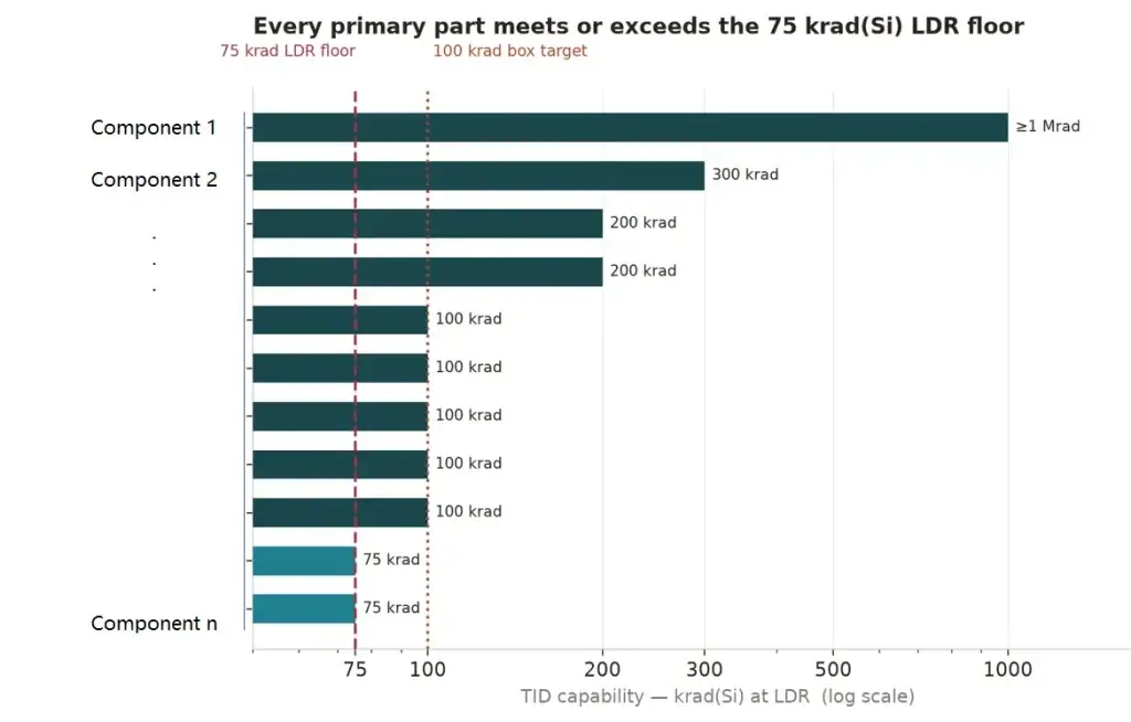
Published TID performance of the principal selected radiation-tolerant components.
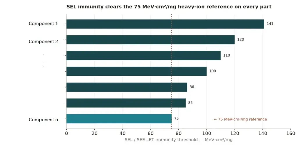
Published destructive-SEE/SEL performance of the principal selected radiation-tolerant components.
4mm Aluminum Shielding and Mission-Dose Boundary
The OBC-HYPER-POLAR enclosure uses a confirmed 4 mm aluminium wall. With an aluminium density of approximately 2.70 g/cm³, the nominal wall represents approximately 1.08 g/cm² areal density before local variations caused by machined pockets, fasteners, connector openings or heat-sink features are considered.
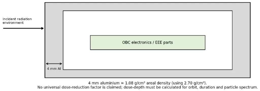
Figure 4 — Shielding geometry used as the mechanical input to mission-specific dose-depth analysis.
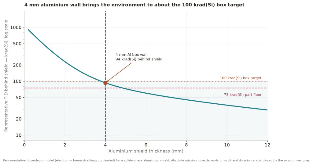
Figure 4a — Representative TID dose-depth attenuation for the 4 mm aluminium enclosure.
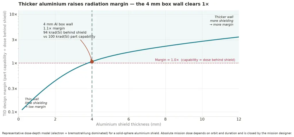
Figure 4b — Representative TID capability margin versus aluminium wall thickness.
The 4 mm aluminium enclosure provides approximately 1.08 g/cm² areal density before local mechanical variations. Figures 4a & 4b reproduce the CAVU product-family representative electron/bremsstrahlung dose-depth basis used in the TCU-RT radiation report: the 4 mm point corresponds to approximately 94 krad in that representative environment and about 1.1× margin against a 100 krad component capability. Absolute mission dose remains dependent on orbit, duration and particle spectrum and is closed by the applicable mission radiation analysis.
Tier Architecture Overview
Tier | Cumulative config. scope | Radiation performance function | Performance boundary |
Base | No RT substitutions | Reference HYPER-POLAR functionality with 4 mm aluminium shielding and retained fault-management features. | Commercial compute/memory/EEE performance is lot- and mission-dependent. |
Tier 0 | Power input/protection, 28→5 V conversion, protected islands, monitoring | Contains destructive power events and provides independently recoverable external power domains. | MPFS460T and memory domains retain Baseline component status. |
Tier 1 | Tier 0 + CAN, RS-422/485, SpaceWire/LVDS, primary clocks | Extends high-radiation component coverage to command/telemetry, SpaceWire and timing functions. | Compute and main-memory component status remains unchanged from the lower tier. |
Tier 2 | Tier 1 + QSPI boot and MSS main memory | Provides redundant >300 krad QSPI boot and 4 GB RT DDR4 with native MSS SECDED. | High-density DDR4 SEE values are controlled below the 75 MeV criterion. |
Tier 3 | Tier 2 + fabric DDR, ADC, dual GbE PHY, bulk-storage protection | Extends RT coverage to fabric memory, precision analogue, Ethernet and recoverable mission-data storage. | DDR and high-capacity storage retain the published boundaries stated in Annex B. |
Tier 4 | Tier 3 + RTPFS460ZT RT PolarFire SoC | Maximum-RT compute configuration with nonvolatile PolarFire configuration immunity. | Tier 2/3 high-density memory and storage boundaries remain applicable. |
Cross-Tier Radiation Performance Summary
Domain | Baseline | T0 | T1 | T2 | T3 | T4 |
Compute core | COTS MPFS460T | same | same | same | same | RTPFS460ZT RT path |
28 V / power | COTS | RT ≥100/78–85 class | same | same | same | same |
Serial / SpaceWire PHY | COTS | COTS | RT 100–300 krad class | same | same | same |
Boot QSPI | COTS dual NOR | same | same | >300 krad rad-hard QSPI | same | same |
MSS main memory | 4 GB LPDDR4 COTS | same | same | 4 GB RT DDR4; 36-bit SECDED; controlled SEE boundary | same | same |
Fabric DDR | 8 GB DDR4 COTS | same | same | same | 8 GB RT DDR4 + ECC/EDAC; controlled SEE boundary | same |
Analogue/temp | COTS | same | same | critical temperature acquisition via RT ADC | RT ADC 75/86 | same |
1 GbE PHY | COTS | same | same | same | RT PHY up to 300/121 | same |
Bulk storage | 2×256GB COTS eMMC | same | same | same | Protected eMMC / space eMMC / RTIMS storage variants | same |
Controlled Performance Boundaries
- Commercial MPFS460T remains the compute device in Baseline through Tier 3. These tiers improve fault tolerance but are not equivalent to a fully RHA compute platform.
- High-density space DDR4 provides 100 krad-class TID capability but the selected 4/8 GB device classes publish SEL thresholds around 61–63 MeV·cm²/mg. HYPER-POLAR RT contains this through SECDED/ECC, protected power islands and autonomous memory recovery.
- No current space mass-storage component reproduces the baseline dual 256 GB eMMC capacity while simultaneously meeting the full 75 krad / 75 MeV component criteria. HYPER-POLAR RT therefore separates critical boot/state from high-capacity mission-data storage and maintains bulk storage as a recoverable fault domain.
- RTPFS460ZT procurement grade and manufacturer radiation evidence is controlled by the exact Tier 4 orderable and the Microchip screening flow referenced in the product EEE file.
- Oscillators, level translators, supervisors, small-signal analogue devices and discrete semiconductors are controlled by exact orderable in the product EEE parts list. This report identifies the dominant radiation-performance devices and product-level containment mechanisms.
Tier Capability Matrix
Tier | Principal hardened domains | Client-visible radiation performance |
Baseline | 4 mm Al enclosure; retained ECC/watchdog/redundancy features | Reference HYPER-POLAR configuration; no blanket component TID/SEL value. |
Tier 0 | 28 V power, protected islands, POL rails, monitoring | Power chain uses 100 krad-class devices with destructive-SEE thresholds at/above the 75 MeV criterion. |
Tier 1 | Tier 0 + CAN, RS-422/485, SpaceWire, 1157R timing | Extends RT component coverage to command/telemetry, SpaceWire and primary clocks. |
Tier 2 | Tier 1 + >300 krad QSPI boot + 4 GB MSS RT DDR4 | Radiation-hardened boot and native 36-bit SECDED main-memory configuration. |
Tier 3 | Tier 2 + 8 GB fabric RT DDR4, precision ADC, dual 1 GbE, protected storage | Completes external-memory/analogue/Ethernet RT coverage and maintains bulk storage as an independently recoverable domain. |
Tier 4 | Tier 3 + RTPFS460ZT RT PolarFire SoC | Maximum-RT compute configuration with nonvolatile configuration immunity and the Tier 3 peripheral protection set. |
Summary
OBC-HYPER-POLAR RT provides a cumulative, client-selectable radiation-performance product family from the baseline HYPER-POLAR architecture through the maximum-RT Tier 4 configuration. Each tier applies radiation-qualified or radiation-characterized devices to a defined set of functional domains while retaining common OBC interfaces, software architecture and autonomous fault-management behavior.
Tier 0 provides radiation-tolerant power containment. Tier 1 adds command/telemetry, SpaceWire and timing components. Tier 2 provides radiation-hardened boot NVM and the 4 GB MSS RT DDR4/SECDED configuration. Tier 3 adds 8 GB fabric RT DDR4 with ECC/EDAC, precision analogue acquisition, dual rad-hard Gigabit Ethernet PHYs and protected bulk-storage configurations. Tier 4 adds the RTPFS460ZT RT PolarFire SoC and provides the maximum-RT compute configuration.
Across the RT product family, boot and recovery state are separated from high-capacity storage; volatile memories and external PHYs are independently supervised and power-contained; ECC/EDAC, watchdogs, redundant interfaces and golden-boot recovery provide layered mitigation of recoverable SEE mechanisms. Manufacturer evidence and controlled performance boundaries are summarized in full report.