Radiation Analysis of Flight Computers: Components TID, SEE and System-Level Radiation Tolerance
- July 23, 2026
- CAVU Aerospace UK
Radiation tolerance is one of the primary design drivers for spacecraft avionics. Unlike terrestrial electronics, flight computers operate in environments where high-energy particles continuously interact with semiconductor devices, potentially degrading their performance or causing immediate failures.
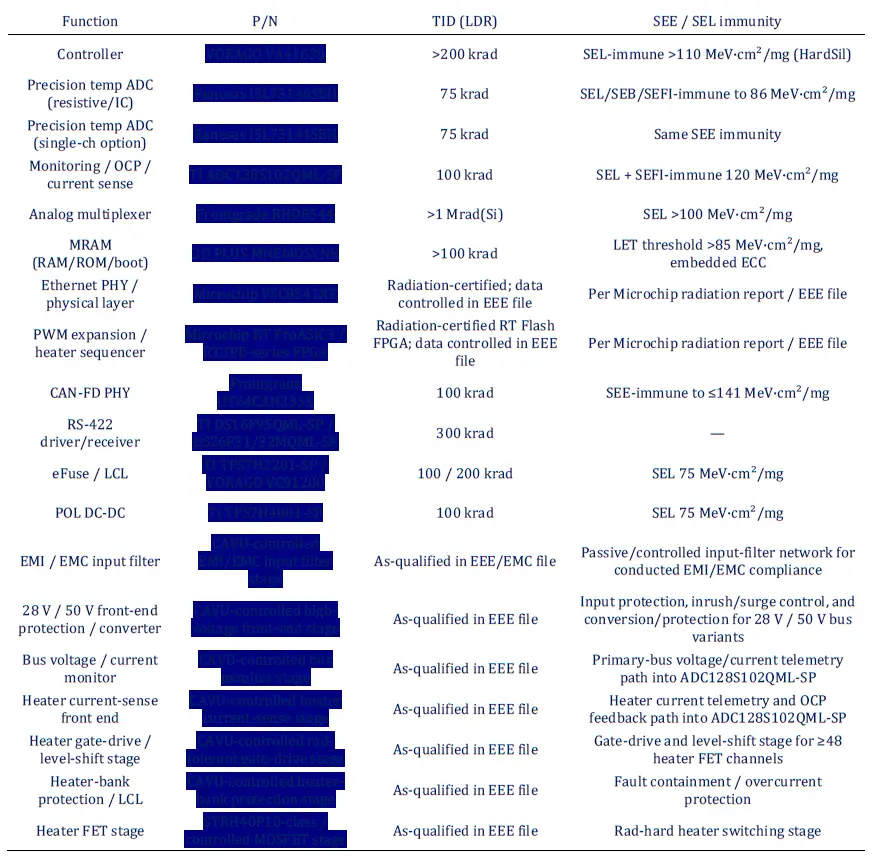
A common misconception is that the radiation capability of a flight computer is determined solely by its most radiation-tolerant component. In reality, the overall radiation tolerance of an onboard computer is determined by the combination of all components, their individual radiation characteristics, system architecture, shielding, redundancy, and fault detection and recovery (FDIR) mechanisms. A comprehensive radiation analysis therefore evaluates every critical component individually before determining the expected radiation performance at the product level.
Example Component Radiation Analysis- TID, SEE & System-level analysis
TID capability of every single component is mapped in a diagram like below.
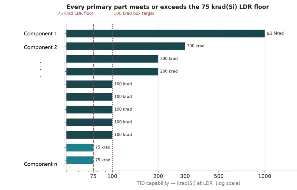
System-level TID analysis generally follows these steps:
- Mission Radiation Analysis- Estimate the accumulated dose using orbit, shielding thickness, mission duration & solar environment.
- Component Database- Every electronic component is assigned manufacturer TID data, radiation test reports, published literature & heritage information.
- Worst-Case Component Review- The component with the lowest qualified TID is identified. However, engineers then determine Is it mission-critical? Is it powered continuously? Is it redundant? Can software compensate for failure? & Is additional shielding practical?
- Margin Assessment- Most space programmes apply radiation design margins.
System-Level SEE Analysis
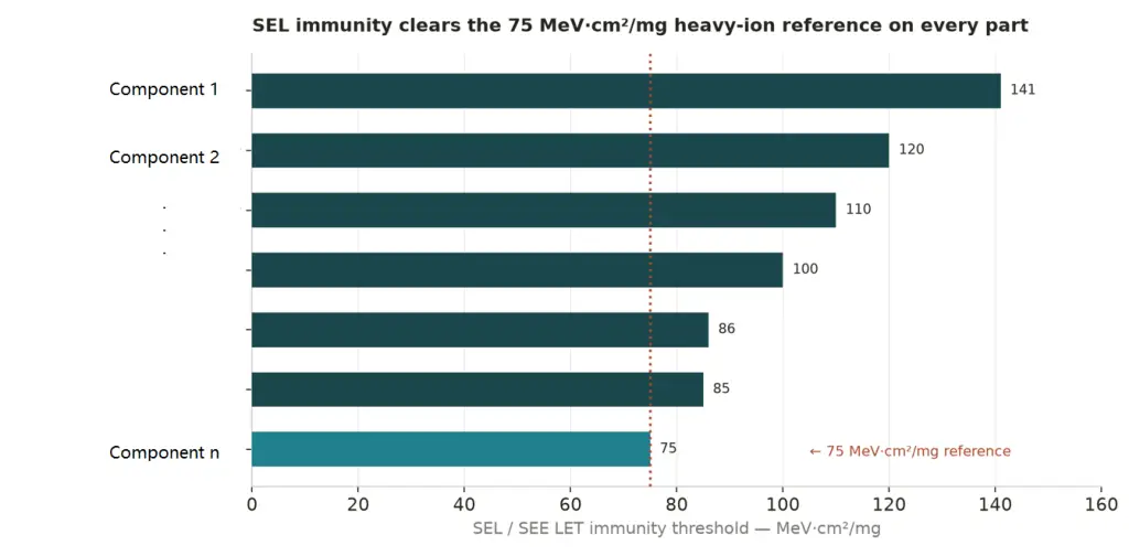
SEE immunity of every single component is mapped in a diagram like below.
Fault Detection, Isolation and Recovery (FDIR)
Modern flight computers increasingly rely on architectural resilience rather than exclusively on radiation-hardened components. Typical FDIR techniques include:
- ECC-protected memory
- Memory scrubbing
- FPGA configuration scrubbing
- Watchdog timers
- Processor lock-step
- Current monitoring
- Automatic latch-up protection
- Safe-mode recovery
- Redundant power supplies
- Error logging and telemetry
Computer manufacturer is supposed to provide FDIR sheet in design procedures.
Results at a glance
We usually provide radiation analysis of product with mission-specific information & taking to account TID capability & SEE immunity of different components and with FDIR mechanism in design, end-user will get to know about system-level tolerance at a glance.