Layered Protection Scheme in Heater Driver Board: Reliable Power Distribution and Intelligent Thermal Control for Spacecraft
- July 27, 2026
- CAVU Aerospace UK
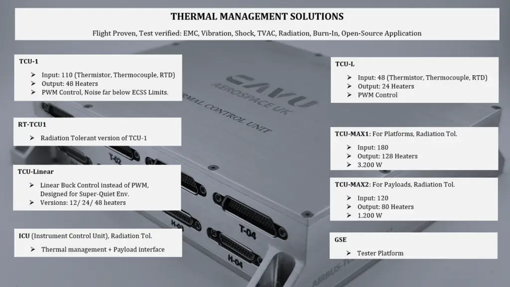
Thermal control is one of the most critical subsystems on any spacecraft. Electronic components, batteries, propulsion systems, optical instruments and scientific payloads all have defined operating temperature limits. Without active thermal management, spacecraft may experience degraded performance, reduced lifetime or complete subsystem failure. A Heater Driver Board provides the controlled electrical power required to maintain spacecraft components within their specified temperature range. By intelligently distributing power to multiple heaters, the driver board forms an essential part of the spacecraft’s thermal control system, ensuring reliable operation throughout launch, eclipse periods and long-duration space missions. The heater driver board shown here illustrates a robust architecture designed for high reliability, low electrical noise and controlled power sequencing while supporting 48 independently controlled heater channels.
To maintain stable operating temperatures, resistive heaters are installed throughout the spacecraft. Typical heater locations can be battery packs, propellant tanks, thruster valves, optical assemblies, reaction wheels, star trackers, cameras, electronics enclosures, mechanisms or antennas. Thermal control unit provides controlled power to these heaters based on commands from the spacecraft’s onboard computer and thermal control software.
TCU Driver Architecture
The architecture of driver board of three major functional sections:
- Protected power input stage
- Local power conversion
- Forty-eight independent heater driver channels
This modular architecture ensures both electrical protection and reliable heater operation.
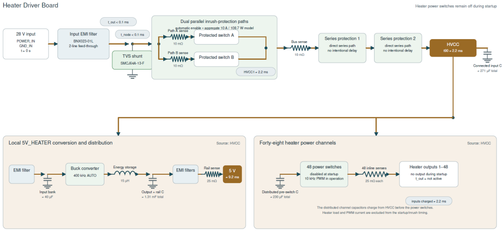
The Heater Driver Board receives power from the spacecraft’s 28 V primary power bus. Before this power reaches the heater outputs, several protection stages are employed.
The incoming power first passes through an EMI feed-through filter. Its purpose is to reduce conducted electromagnetic interference, prevent switching noise entering the spacecraft power bus & improve EMC compliance.
A Transient Voltage Suppressor diode is also placed to protect the electronics from voltage spikes, switching transients, load dump events or any electrostatic discharge. This significantly improves system robustness.
One of the most interesting features of the design is the dual parallel inrush-protection paths. Rather than connecting the spacecraft power bus directly to the large onboard capacitors, the design limits startup current using two protected switch paths. Each path has current sensing, controlled switching, low-value sense resistor and automatic enable circuitry.
It provides reduced inrush current, protection of spacecraft power bus, prevention of voltage collapse, reduced stress on connectors and improved system reliability. Once the capacitors have charged, the protection circuitry allows full current flow with minimal voltage drop.
Following the inrush stage, additional series protection provides another layer of fault isolation. These protection devices help protect against short circuits, internal failures, excessive current or any abnormal operating conditions. This layered approach is common in high-reliability aerospace electronics where single-point failures must be minimised.
After completing the startup sequence, power is distributed onto the internal HVCC power rail. This high-current distribution bus supplies heater channels, local power converter & monitoring circuitry. Separating the protected power rail from the external spacecraft bus simplifies fault isolation and improves system reliability.
Although the heater channels operate directly from the spacecraft power bus, the control electronics require a regulated low-voltage supply. The heater driver board therefore includes its own onboard power conversion stage. This consists of EMI filter, High-efficiency buck converter, Energy-storage inductor, Output capacitors & Additional EMI filterings.
The result is a clean 5 V rail powering microcontrollers, digital logic, monitoring circuits, communication interfaces & PWM control electronics. By generating this supply locally, the board reduces dependence on external power converters while improving noise immunity.
Forty-Eight Independent Heater Channels
The primary function of the board is to control 48 individual heater outputs. Each heater channel contains power switch, current sensing resistor, output monitoring, PWM capability and protection circuitry. Each channel can be independently enabled or disabled by the spacecraft flight computer. This architecture allows different spacecraft components to maintain completely independent temperature set points.
PWM vs. Linear Control
Instead of simply switching heaters fully on or off, modern Heater Driver Boards often regulate power using Pulse Width Modulation. PWM rapidly switches the heater between ON and OFF states while varying the duty cycle. Advantages are precise temperature regulation, improved efficiency, reduced thermal overshoot, lower average power consumption & smoother thermal control. Each heater can therefore deliver exactly the amount of heat required by the spacecraft. The only concern might be EMC which we took TCU to number of EMC tests & proved to be way below ECSS thresholds.
Linear buck control driver is a solution for super quiet environments. Sensitive payloads such as high-resolution optical instruments, scientific detectors, infrared imaging systems, magnetometers, low-noise radio receivers, precision analogue electronics or quantum sensing experiments, can be affected by the switching noise generated by PWM-controlled heaters. Although PWM frequencies are typically chosen to minimise interference and extensive filtering is employed, the rapid switching of large heater currents can still introduce conducted and radiated electromagnetic noise that may degrade the performance of extremely sensitive instruments.
For these applications, an alternative approach known as Linear Buck Control (also referred to as linear current regulation or linear heater control) can be used. Unlike PWM, where the heater is repeatedly switched fully ON and OFF, Linear Buck Control continuously adjusts the voltage or current delivered to the heater. The control element operates in its linear region, providing only the power required to maintain the desired temperature.
This approach offers several important advantages like virtually no switching noise and minimal conducted and radiated electromagnetic emissions.
Because the heater current changes continuously rather than in discrete pulses, the electrical environment remains exceptionally quiet. This is particularly beneficial when heaters are located close to precision analogue electronics or optical detectors where even small amounts of electrical interference can reduce measurement accuracy.
Current Monitoring
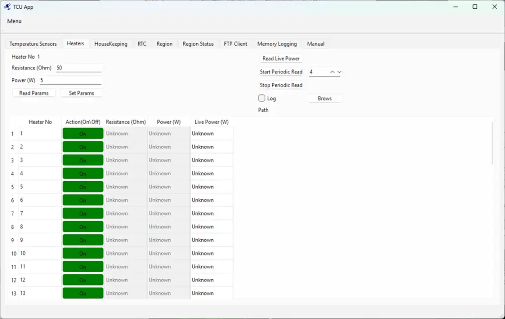
Every heater channel incorporates current sensing. Continuous current measurement allows the onboard computer to detect open-circuit heaters, short circuits or wiring faults.
Reliability Through Redundancy and Protection
Spacecraft electronics must continue operating reliably throughout years of thermal cycling, vibration and radiation exposure. The heater driver board therefore incorporates multiple layers of protection, including EMI filtering, transient voltage suppression, controlled inrush current limiting & parallel protected switching paths. Together, these features improve robustness while protecting both the Heater Driver Board and the spacecraft power system.