External magnetic-isolation board on OBC-Cube-Polar
- June 11, 2026
- CAVU Aerospace UK
The Standard version of OBC-Cube-Polar 1G Ethernet outputs is implemented as compact capacitively-coupled Ethernet interfaces from 10/100/1000 voltage-mode copper PHYs. If the satellite platform requires galvanic isolation, the clean solution is to add a small external magnetic-isolation adapter connected to J3/J4. The OBC PCB itself does not need to be enlarged or re-laid out. For this situation we have an adapter add-on card. The proposed adapter is a passive interface board. It does not require an additional active Ethernet PHY or switch IC. The active Ethernet PHY remains on the OBC; the adapter board adds the isolation magnetics and the final satellite-bus connector interface.
Existing OBC interface at J3/J4
Each of J3 and J4 carries one 1G Ethernet MDI interface using four differential pairs. The pin allocation is shown below and is repeated for both Ethernet ports.
MDI pair | Positive pin | Negative pin |
Pair A | Pin 1: A_P | Pin 9: A_N |
Pair B | Pin 3: B_P | Pin 11: B_N |
Pair C | Pin 5: C_P | Pin 13: C_N |
Pair D | Pin 7: D_P | Pin 15: D_N |
Unused / no connection | Pins 2, 4, 6, 8, 10, 12, 14 | – |
Connector on OBC | Nano-D 15-way | J3 = Ethernet 1, J4 = Ethernet 2 |
OBC connector part | A29100-015 | – |
Mating connector | A28000-015 | – |
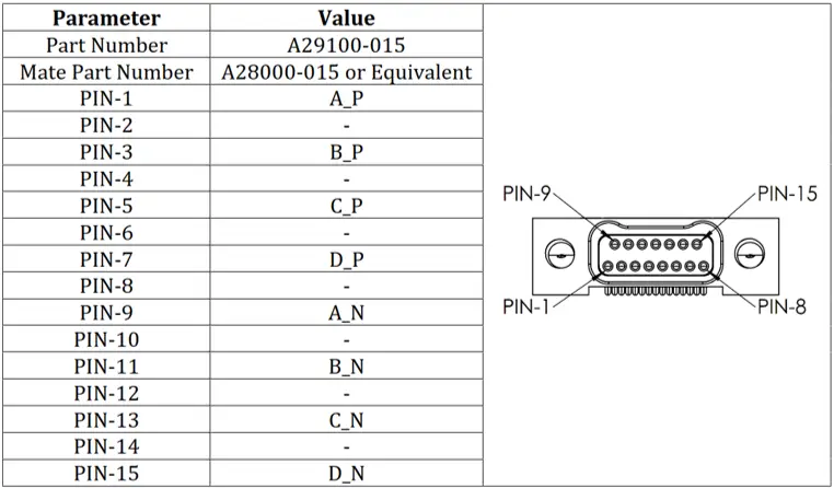
J3/J4 Ethernet Nano-D pinout reference.
External magnetic-isolation adapter concept
Item | Description |
Input side | Two connectors mate to OBC J3 and J4. These carry the four MDI pairs for Ethernet 1 and Ethernet 2. |
Isolation stage | Two single-port Gigabit Ethernet magnetics/transformer modules are fitted on the mini-board: one for Ethernet 1 and one for Ethernet 2. |
Output side | Two isolated Ethernet output connectors are provided for connection to the satellite bus or harness. |
Connector options | The satellite-side connector type is selectable. The board can use Nano-D, Micro-D, RJ45 for lab/GSE use, or a mission-specific connector, subject to mechanical and harness constraints. |
Mounting | The adapter can be shaped to mount close to the OBC, on the OBC stack, or elsewhere nearby in the satellite, subject to harness length and mechanical constraints. |
Candidate magnetics / transformer options
The adapter board can be built using either of the following candidate single-port Gigabit Ethernet magnetics modules, or an equivalent device selected against the final isolation, temperature, mechanical, and procurement requirements:
Candidate device | Type | Use on adapter | Notes |
WE-749023015 | Single-port 1000BASE-T LAN magnetics / transformer module | One per Ethernet port | Candidate part. |
Pulse HX5120NLT | Single-port 1000BASE-T LAN magnetics / transformer module | One per Ethernet port | Candidate low-profile SMT part. |
Note: These are passive magnetics, not active PHY chips. Therefore, the board does not add another Ethernet controller; it only adds the isolation transformer function, common-mode/noise control, termination/protection, and the required output connectorization.
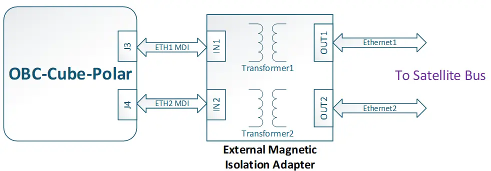
Functional arrangement of the external magnetic-isolation adapter.
Electrical topology
The adapter implements the following functional path for each Ethernet port:
OBC PHY → J3/J4 MDI pairs → adapter input connector → Gigabit Ethernet magnetics → isolated output connector → satellite bus/harness
- The OBC Ethernet PHY is a 10/100/1000 voltage-mode copper PHY operating in SGMII-to-copper mode from the PolarFire SoC GEM MAC.
- The four MDI pairs from J3/J4 are carried to the adapter board as controlled 100-ohm differential pairs.
- The magnetics provide the galvanic isolation boundary between the OBC-side Ethernet domain and the satellite-side Ethernet harness/interface.
- The termination, shield, ESD, and connector-shell treatment on the output side can be adapted to the satellite grounding and EMC approach.
- The mini-board can be made as a compact passive board and mechanically fixed close to the OBC to minimize the non-isolated MDI extension length.
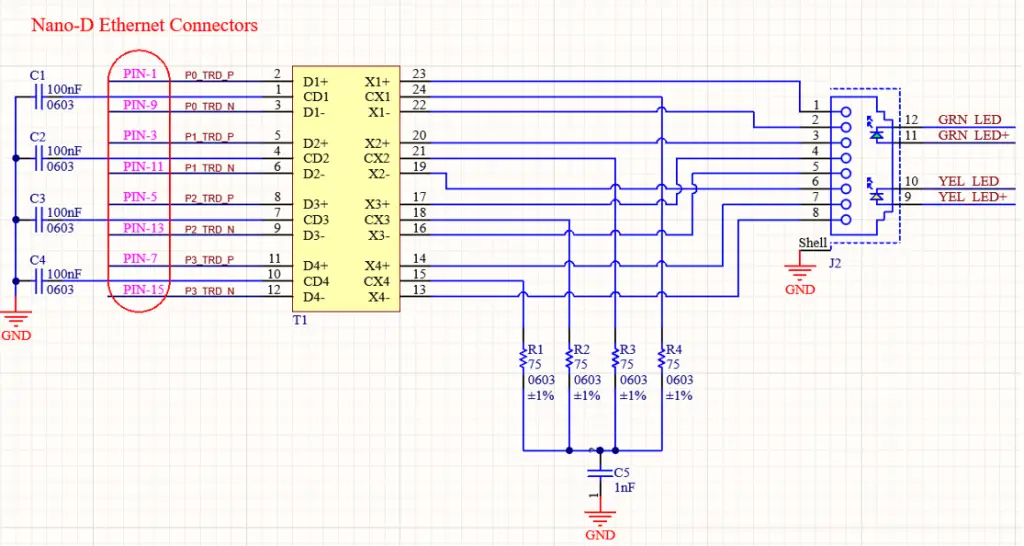
Example single-port magnetics schematic block for one J3/J4 Ethernet interface.