Current limit for the input/output GPIO pins of OBC-Cube-Polar
- June 5, 2026
- CAVU Aerospace UK
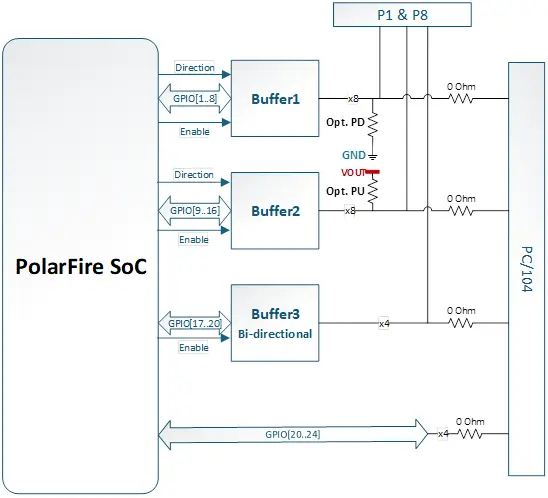
The 24 GPIOs in OBC-Cube-Polar are split into four electrical groups:
GPIO group | Implementation | Recommended board rating | Important limit |
GPIO[1..8] | 8-bit buffer IC | 20 mA per pin | 100 mA total across the buffer IC |
GPIO[9..16] | 8-bit buffer IC | 20 mA per pin | 100 mA total across the buffer IC |
GPIO[17..20] | 4-bit translator / buffer IC | 20 mA per pin, conservative | 100 mA total across the translator IC |
GPIO[21..24] | Direct 3.3 V SoC GPIO bank | 16 mA per pin | Use with margin; not intended as load drivers |
For the buffered groups, the key point is that the per-pin current is not the only limit. The total current through each buffer IC must also remain within the aggregate limit.
For example, three pins in GPIO[1..8] each driving 15 mA is acceptable because the total is 45 mA. However, six pins each driving 20 mA would total 120 mA, which exceeds the aggregate 100 mA limit for that buffer group.
Also, GPIO[17..20] are suitable for digital signalling and level translation, but they should not be used as power drivers. For any load-like device, we recommend using an external transistor, MOSFET, or driver stage. This is the high level block diagram of all 24 GPIOs: