
Beyond the Hardware: The Documentation Package & Harness Coming with a Flight-Ready On-Board Computer
- October 2, 2026
- CAVU Aerospace UK
An onboard computer is one of the most critical electronic systems on a spacecraft. It is responsible for executing software, managing spacecraft functions, handling data, communicating with other subsystems and, in many missions, supporting autonomous fault detection and recovery. However, delivering a flight-ready onboard computer is about much more than delivering the hardware itself. We provide a complete harness package that end-users need during development & its included in price. A typical items package list for an onboard computer is as following:
No. | CAVU Ref. | Quantity | Part Number | Description |
1 | CAVUK-C-2510-16-OBCP001 | 1 | JPL-OBCP-03 | OBC-Hyper-Polar Module- Std. |
2 | CAVUK-C-2510-16-OBCP002 | 1 | GMPMBT2-B-EM & GMPM2-B112PSM | Micro-D 2-pin power cable set |
3 | CAVUK-C-2510-16-OBCP003 | 1 | MDM-15SH003B | Micro-D 15-pin to Sub-D15 pin Debug connector-cable set |
4 | CAVUK-C-2510-16-OBCP004 | 1 | MDM-25PH003K | Micro-D 25-pin connector-cable |
5 | CAVUK-C-2510-16-OBCP005 | 1 | M83513/04-H11N | Micro-D 100-pin connector-cable |
6 | CAVUK-C-2510-16-OBCP006 | 2 | MDM-9SH003K | Micro-D 9-pin connector-cable |
7 | CAVUK-C-2510-16-OBCP007 | 1 | MDM-9PH003B | Micro-D 9-pin connector-cable |
7 | CAVUK-C-2510-16-OBCP008 | 1 | FlashPro 5 | Programmer |
8 | CAVUK-C-2510-16-OBCP009 | 1 | N/A | CAVU Debug Board (JTAG/USB/Serial) |
9 | CAVUK-C-2510-16-OBCP010 | 1 | N/A | Documents |
For a spacecraft manufacturer or system integrator, the OBC must come with the engineering information necessary to integrate, configure, operate, verify and ultimately qualify the equipment for its mission. A comprehensive documentation package provides this information and gives the customer confidence that the hardware is understood, controlled and supported throughout its lifecycle. This approach is consistent with the philosophy of the ECSS, where engineering, product assurance, dependability, configuration management and verification form interconnected parts of the space product lifecycle.
More Than a User Manual
A commercial electronic product may be supplied with a datasheet and a user manual. A spacecraft OBC requires a much deeper level of documentation.
The customer needs to access basic documents for development in software & also hardware integration. Its definitely beyond ICD & User Guide. A properly structured OBC documentation package answers these questions and creates a technical record connecting the design, manufacturing, verification and delivered flight hardware. Other than documents like datasheet, ICD (sometimes several ICD for interfaces like SpaceWire, CameraLink etc), User Guide, PAP, QAP, End Item Data Package, Certificate of Conformance & test report, we provide basic technical docs like FMEA, CIL, FDIR, Reliability Assessment, Radiation Analysis, Mechanical analysis, Fault Tree Map, Materials & Process list. For software development on the other hand, most of user guide, Q&A & debugging sessions are happening in CAVU GitLab.
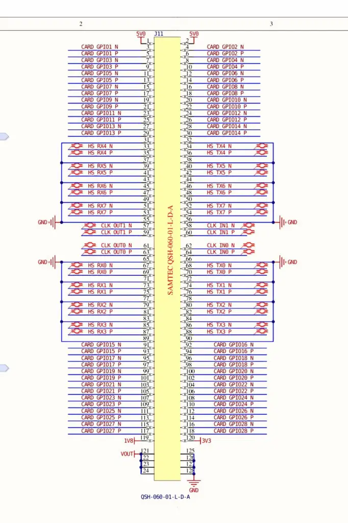
The Interface Control Document, ICD defines how the OBC interfaces with the spacecraft. This can include electrical interfaces, power requirements, communication interfaces, mechanical interfaces, connectors, signals, data protocols and other spacecraft-level interfaces. For many products we also have separate ICDs for software, interfaces like SpaceWire or ICD for Samtec B2B connectors in case client needs to access Samtec for further integration.
Declare Process List & Manufacturing and Product Configuration Documentation
Documents such as the MPMPL provide important information about the manufacturing and configuration of the product. For a flight unit, knowing what was actually manufactured is just as important as knowing what was originally designed. Space projects therefore place strong emphasis on configuration management. ECSS configuration-management guidance addresses the identification of configuration items, documentation, baselines, changes and the as-built configuration. This allows the customer to maintain traceability between the design, manufacturing process, delivered hardware and supporting documentation.
FMEA — Understanding How the OBC Can Fail
The Failure Modes and Effects Analysis examines potential failure modes and their consequences. For an OBC, this can extend from individual components and circuits through functional blocks and ultimately to the equipment-level consequences. The purpose is not simply to create a list of possible failures. Usually along with FMEA, we provide both functionals & physical block diagram of products which is helping in both FMEA, FDIR & Reliability assessment. FMEA helps engineers understand:
What can fail → how can it fail → what is the consequence → can the failure be detected → can it be controlled or mitigated?
ECSS specifically identifies FMEA/FMECA as a dependability activity intended to support mission performance, dependability and safety objectives. It also identifies its relationship with redundancy, critical items and FDIR. For redundant OBC architectures, this analysis becomes particularly valuable because it can demonstrate how the system responds when one computing element becomes unavailable.
A typical FMEA sheet for an OBC can be a sheet with more than 100 failure modes & more than 20 columns to cover ECSS requirements.
CIL — Critical Item List
The Critical Item List (CIL) identifies items that require particular attention because of their potential impact on mission performance, safety or reliability. The CIL provides the customer with visibility of critical aspects of the OBC design and supports the wider spacecraft dependability and product-assurance process. This is especially important for equipment containing high-value or mission-critical functions.
FDIR — Fault Detection, Isolation and Recovery
A spacecraft cannot rely only on preventing failures. It must also be capable of responding to failures when they occur. The FDIR documentation describes how faults can be detected, isolated and recovered. For example, a fault may be detected through monitoring of Processor health, Power rails, Communication interfaces, Memory status, Watchdogs, Temperature, Internal telemetry & Software or hardware health indicators. FDIR is probably most important documents manufacturer is providing to system integrator to show how system can then take an appropriate recovery action for an end user.
For a redundant OBC architecture, this could include switching operation from the active OBC to the redundant unit. This is where reliability analysis and system architecture come together. ECSS guidance explicitly identifies FMEA/FMECA as an input to FDIR design and requires analysis of how anticipated failure modes can be detected and controlled.
Reliability Assessment
The Reliability Assessment provides an engineering assessment of the expected reliability of the OBC. It can consider component reliability, operating conditions, environmental stresses, derating, architecture and other relevant factors. For the spacecraft customer, this provides quantitative engineering evidence supporting the use of the OBC in the mission. For architectures such as a dual-redundant CDH system, reliability analysis can go one step further by considering the contribution of redundancy to overall system availability and reliability.
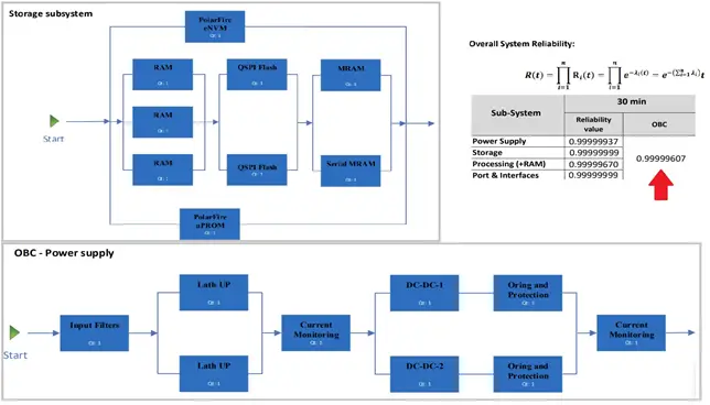
Obviously for this analysis we take into account orbit, profile & duration of missions, but as most of the times end-users are in early stage of development & they don’t have much idea about data, we consider a LEO mission with 3 years lifetime in 400km orbit.
Radiation Analysis
Radiation is one of the fundamental environmental challenges for spacecraft electronics. The Radiation Analysis documents the expected radiation environment and the OBC’s susceptibility or resistance to relevant radiation effects. Depending on the product and mission, this may include Total Ionising Dose (TID), Single Event Effects (SEE), Single Event Upsets (SEU), Single Event Latch-up (SEL), Single Event Functional Interrupts (SEFI) & Radiation-induced degradation.
For spaceborne computing systems, radiation performance is particularly important because failures caused by radiation can affect both hardware and software behaviour. ESA notes that reliability and radiation tolerance are specific concerns for microelectronics used in spacecraft. In LEO missions with COTS components radiation can be guaranteed up to 30kRad & 60 MeV while for a Radiation tolerant product it can be 100 kRad & 86 MeV. For LEO missions, we usually focus on TID as we cannot do much about SEE.
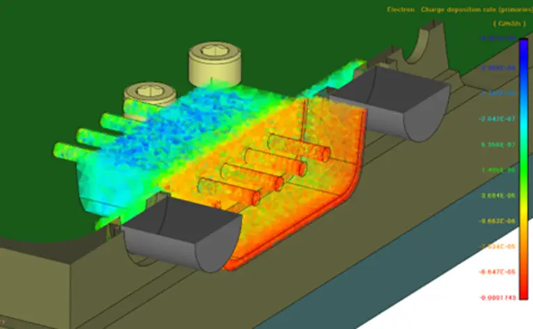
For Radiation Tolerant products, we obviously have to consider both TID & SEE & provide a break-down analysis of components in radiation analysis & provide minimum system tolerance which usually can guarantee different level of kRad & MeV in different tiers of RT on components.
Mechanical & Thermal Analysis
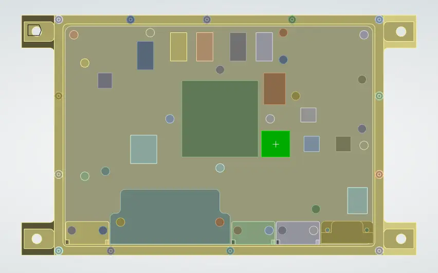
The Mechanical Analysis demonstrates that the OBC is mechanically suitable for its intended spacecraft environment. Depending on mission requirements, this can include assessment of Structural integrity, Launch vibration, Shock, Mechanical loads, Natural frequencies, Mounting configuration & Thermal-mechanical effects. This gives the spacecraft designer confidence that the OBC can survive the mechanical environment associated with launch and operation.
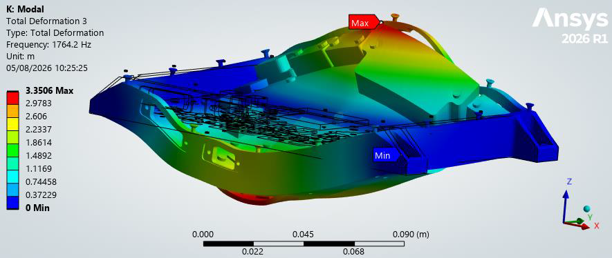
In case of AI-enables onboard computers where we pair FPGA with NVIDIA Jetson GPUs, we also have to provide thermal analysis to help system integrators with best possible fit of OBC into platform & harness.
PAP and QAP — Product and Quality Assurance
The Product Assurance Plan (PAP) and Quality Assurance Plan (QAP) describe the processes used to control product quality and assurance throughout development and manufacturing. These documents are important because reliability is not created by testing alone. It is created through a controlled process covering design, component selection, manufacturing, inspection, testing, configuration management and non-conformance control.
ECSS maintains dedicated standards covering product assurance, quality assurance, critical-item control and nonconformance control.
End Item Data Package — The Record of What’s Delivered
The End Item Data Package brings together the information needed to establish the configuration and verification status of the delivered hardware. It provides a record of the actual flight item rather than simply describing the generic product. This distinction is important. An OBC may have a product design that exists across multiple units, but the customer ultimately needs to know:
Certificate of Conformance
The Certificate of Conformance (CoC) formally confirms that the delivered product conforms to the applicable requirements and agreed configuration. It provides a concise quality record accompanying the hardware and complements the detailed engineering documentation.
Test Reports
Depending on the product and project, the test documentation can cover areas such as:
- Functional test sheets
- EMI/ EMC tests
- Thermal-vacuum testing
- Vibration
- Shock
- Burn-in
- Environmental testing
- Performance verification especially in case of Camera
ECSS verification requirements establish verification as a structured process and apply it from individual equipment through to complete space systems.
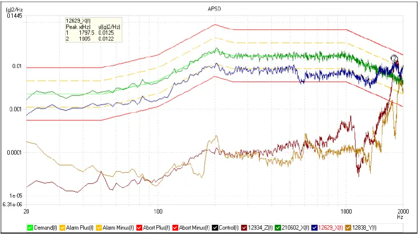
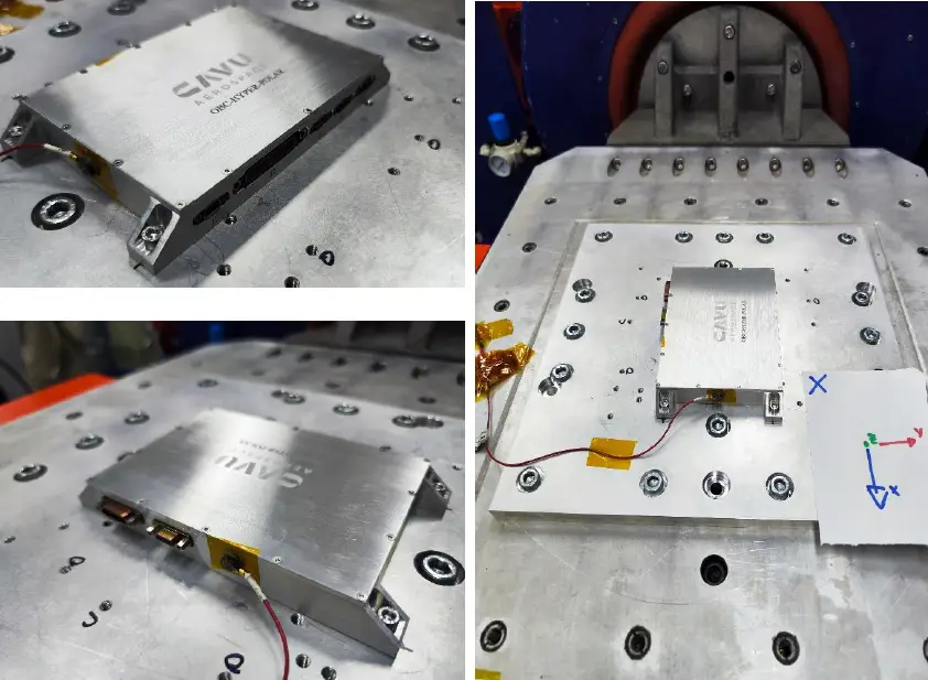
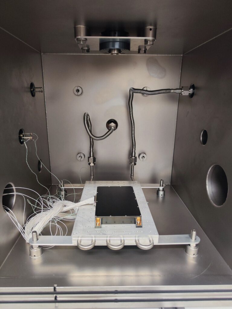
Above mentioned docs & harnesses are usually included in delivery package of CAVU onboard computers. For complete set of documentation according to ECSS/ NASA, we usually send document list of products & users tick the box & we put it in scope of the job during project development.