HTP in Thermal Control Unit using Classic CAN
- September 8, 2026
- CAVU Aerospace UK
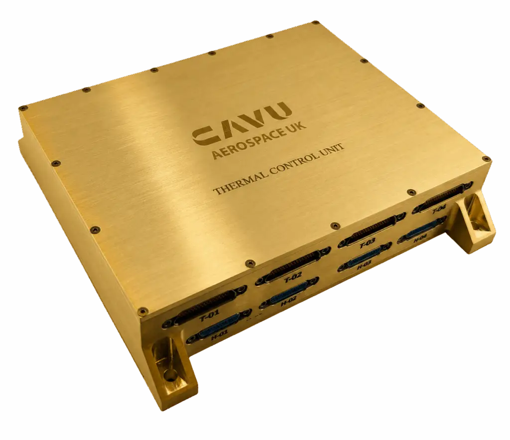
One of the popular spec. of TCU is advanced networking capabilities like Ethernet, CAN which effectively helps project developers to not only drive heaters, solenoids, valves etc, but also talk to other sub-systems when they need to. WE do have specific more detailed ICD for TCU CAN & Ethernet which provides details but in this article we show how carrying HTP over CAN in Thermal Control Unit works & specifically how HTP packets are fragmented across CAN frames and reassembled.
HTP is carried using Classic CAN extended 29-bit data frames. Both TCU CAN buses use the same identifiers:
- Host → TCU requests and flow control: 0x18DA01F1 by default
- TCU → Host responses and flow control: 0x18DAF101 by default
The identifiers are configurable through the serial interface using command 0x50 and readable using 0x51.
Before fragmentation, an HTP packet is:
Source | Destination | Command | Payload length MSB | Payload length LSB | Payload | CRC-8
The total packet length is payload length + 6. CRC-8 uses polynomial 0xEB, initial value 0x00, and covers the complete binary packet except the CRC byte.
CAN fragmentation uses ISO 15765-2-style PCI bytes:
- Single frame: 0x0L, followed by up to seven HTP bytes
- First frame: 0x1H LL, followed by the first six HTP bytes
- Consecutive frame: 0x2N, followed by up to seven HTP bytes
- Flow control: 0x3S BS STmin
Sequence numbers start at 1 and wrap 1…15, 0, 1…. All CAN frames use DLC 8 and 0xCC padding.
For a fragmented request, the TCU normally returns:
30 08 00 CC CC CC CC CC
This permits eight consecutive frames with zero separation before another flow-control frame is required. Fragmented responses work in the opposite direction: the host sends flow control to the TCU. The flow-control and consecutive-frame timeout is one second.
Reassembly uses the 12-bit packet length in the first frame. The receiver appends the first six bytes and then seven bytes from each correctly sequenced consecutive frame until the declared length is reached. It then verifies the embedded payload length, CRC, and HTP destination address before dispatching the packet.
Redundant thermistors
Each region configuration contains:
- A primary thermistor list
- A redundant thermistor list
- A heater list
- Low and high temperature thresholds
- A control type selecting minimum or mean temperature
The redundant thermistor list can be configured and read through the interface.
Heater handling:
A region can contain multiple heater channels. When automatic control is enabled, all heaters assigned to that region are operated together:
- Control temperature below the low threshold: all assigned heaters turn on.
- Control temperature above the high threshold: all assigned heaters turn off.
- Temperature between the thresholds: heater states remain unchanged.
The firmware monitors active-heater current and reports low-current or high-current alarms, but the alarm can automatically isolate the heater or enable another heater.
A heater should not be assigned to multiple automatically controlled regions unless the system design explicitly coordinates them, because there is no conflict arbitration between regions.
Direct control and automatic control
A direct heater command takes effect immediately. If that heater belongs to a region whose automatic control remains enabled, the next region-control cycle may change it again. The recommended sequence for manual operation is:
- Disable automatic control for every region that can command the heater.
- Apply the required heater state.
- Read the heater state for confirmation.
- Re-enable automatic control when required.
Disabling automatic control does not itself turn the associated heaters off.
Configuration changes during operation
Thermal and region configuration commands write directly into the active configuration area. There is no separate staging configuration or commit operation. Region-control processing reads this area periodically, so accepted settings normally affect the next control cycle.
Configuration updates are not atomic relative to the periodic control interrupt. The recommended operational procedure is therefore:
- Disable automatic control for the affected region.
- Establish a known safe heater state.
- Write the complete configuration.
- Read the configuration back and verify it.
- Re-enable automatic control.
Configuration persistence
CAN configuration is persistent. It is stored in two sequence-numbered, CRC-protected FRAM records. On startup, the TCU selects the newest valid record. If neither record is valid, it uses the compiled CAN defaults.
In the current firmware build, the remaining settings behave differently:
- Thermistor parameters are restored from compiled defaults at every startup.
- Heater parameters are restored from compiled defaults at every startup.
- Region settings are restored from compiled defaults because RESET_REGIONS is enabled.
- Automatic-control enable states are volatile and are enabled for all regions during startup.
- Direct heater states are volatile and initialise to off.
- Region historical maximum-power values are volatile and reset at startup.
Startup and reset
During startup the TCU:
- Initializes the serial interfaces and peripheral hardware.
- Initializes the heater PWM controllers.
- Loads the thermistor and heater parameters.
- Restores the region configuration.
- Starts temperature acquisition and control timing.
- Loads the CAN configuration from FRAM, or uses CAN defaults if no valid record exists.
- Enables automatic control for all regions.
Heater software states initially start off. Once valid temperature acquisition begins, the automatic-control loop may turn assigned heaters on according to the configured thresholds.
Command 0x39 restores all region definitions to their compiled defaults. It does not reset heater outputs, heater electrical parameters, thermistor parameters, automatic-control flags, or historical region status.
Command 0x3C only clears the historical highest-power value for one region or all regions; it does not change the operational configuration or heater states.