
Redundant OBC Architecture & Supervisor for High-Reliability Spacecraft
- August 20, 2026
- CAVU Aerospace UK
One effective approach to improving spacecraft reliability is the implementation of a double OBC architecture, in which two independent OBCs are available to perform the critical spacecraft computing and control functions. However, redundancy alone is not sufficient. The spacecraft also requires an independent and reliable mechanism to control which OBC is active, recover from faults, manage power, and perform a controlled transition from one OBC to the other. This role can be performed by a dedicated Supervisor, providing a simple and deterministic management layer above the two OBCs.
The Supervisor algorithm defines the decision-making and operational logic, while the hardware implementation can be realised either as an add-on card positioned between the two OBCs or as a separate supervisor board connected independently to both OBCs.
Dual-OBC Redundancy
In a typical redundant architecture, the spacecraft contains:
- OBC-A
- OBC-B
- A dedicated Supervisor
- Controlled power paths
- Reset and enable signals
- Health-monitoring interfaces
- Communication interfaces between the Supervisor and each OBC
At any given time, one OBC can operate as the Active OBC, responsible for controlling the spacecraft and executing the primary mission or platform software. The second unit can remain in one of several states, depending on the mission requirements:
- Cold redundancy – the backup OBC is completely powered off.
- Warm redundancy – selected circuits or subsystems remain powered, allowing faster activation.
- Hot redundancy – both OBCs are powered and operational, with one designated as the active controller.
The Supervisor provides the mechanism required to manage these states safely and predictably.
The Supervisor is not intended to replace the computational capability of the OBC. Instead, it performs a focused set of critical management functions that remain available even if the active OBC experiences a software or hardware failure.
A key function of the Supervisor is determining which OBC has authority to control the spacecraft. The Supervisor maintains a clear definition of:
- Active OBC
- Standby OBC
- Failed OBC
- Recovery or maintenance state
Only the selected Active OBC should have control authority over critical spacecraft interfaces. Depending on the spacecraft architecture, the Supervisor can control the selection using Enable signals, Multiplexers, Bus switches, GPIO control, Communication routing, Power-domain switching & Interface isolation.
This architecture helps prevent a situation in which both OBCs simultaneously attempt to control the same spacecraft subsystem. During normal operation, the Supervisor may keep OBC-A active and OBC-B in standby. If OBC-A experiences a critical fault, the Supervisor can isolate or power down OBC-A, activate OBC-B, and transfer control to the redundant computer.
Health Monitoring
Health monitoring provides the information required by the Supervisor to determine whether an OBC is operating correctly. Typical monitoring mechanisms may include hardware watchdog signals, periodic heartbeat signals, GPIO health indicators, power-good signals, voltage monitoring, current monitoring, Temperature reading, internal error flags, communication status & FPGA or processor status.
For example, the active OBC can periodically generate a heartbeat signal to the Supervisor. As long as the heartbeat arrives within the expected timing window, the Supervisor considers the OBC operational. If the heartbeat is missing, the Supervisor can initiate a predefined recovery sequence.
A typical recovery sequence could be:
- Detect missing heartbeat from the active OBC.
- Wait for a defined confirmation period to avoid false fault detection.
- Issue a reset command to the affected OBC.
- Monitor whether normal heartbeat operation returns.
- If recovery fails, perform a power cycle.
- If the OBC remains unavailable, isolate it.
- Power ON or activate the redundant OBC.
- Confirm successful boot and health status.
- Transfer Active OBC authority to the redundant unit.
- Report the failure to spacecraft telemetry when communication is available.
This hierarchical recovery approach avoids unnecessary failover while ensuring that a persistent failure can be handled autonomously.
Supervisor Algorithm
The Supervisor behaviour can be implemented as a deterministic state machine.
A simplified architecture may include the following states:
Initialisation- After spacecraft power-up, the Supervisor verifies its own power and configuration, determines the initial OBC configuration, and begins the selected startup sequence.
Primary OBC Startup- The Supervisor powers the selected primary OBC and maintains it in reset until all required power rails are stable. The reset is then released, and the Supervisor begins monitoring the OBC health indicators.
Normal Operation- The selected OBC operates as the Active OBC. The Supervisor continuously or periodically monitors Heartbeat, Watchdog, Power status, Temperature & Fault flags. The redundant OBC remains in its configured standby mode.
Fault Detection- If the active OBC fails to satisfy the defined health criteria, the Supervisor enters a fault-handling state. The fault may be classified as Temporary, Recoverable, Persistent & Critical.
Recovery- Depending on the fault classification, the Supervisor can attempt Software reset request, Hardware reset, Peripheral reset & Complete OBC power cycle.
Failover- If recovery is unsuccessful, the Supervisor isolates the failed OBC and activates the redundant OBC. The redundant OBC becomes the new Active OBC.
Continued Operation- The Supervisor continues monitoring the newly active OBC while maintaining the failed unit in a safe state. Depending on the mission requirements, it may periodically attempt to recover the failed OBC and return it to standby availability.
Hardware Implementation Option 1: Supervisor as an Add-On Card
One implementation approach is to integrate the Supervisor into an add-on card positioned between the two OBCs. In this architecture, the add-on card provides the electrical and logical connection required to manage both computers.
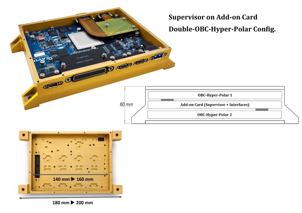
The architecture can effectively create a redundancy management layer between the two computing units. This can be particularly attractive for modular spacecraft avionics where two OBCs are installed in a common mechanical stack.
Hardware Implementation Option 2: Separate Supervisor Board
Alternatively, the Supervisor can be implemented as an independent board connected to both OBCs. In this architecture, the Supervisor is physically separated from the redundant computers and communicates with each OBC through dedicated interfaces. The separate Supervisor board can independently connect to OBC-A, OBC-B, Spacecraft power distribution, Critical spacecraft interfaces & Telemetry systems.
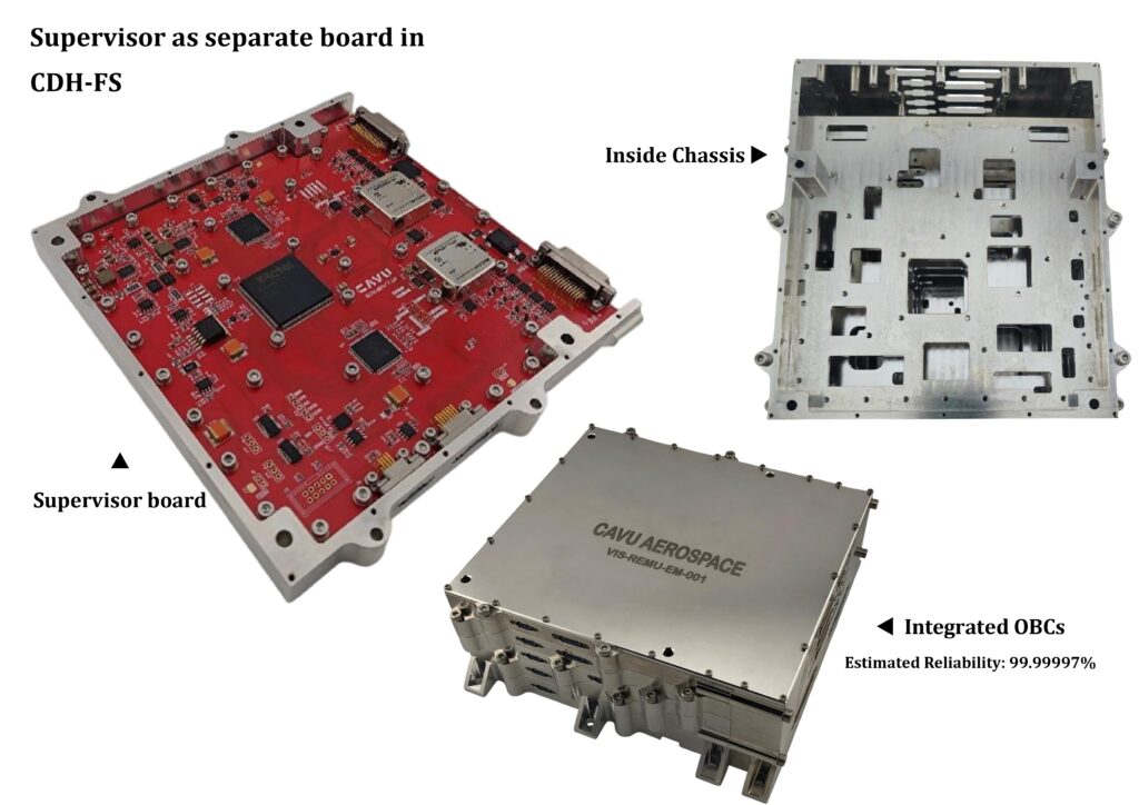
A separate Supervisor can therefore act as an independent avionics management authority responsible for maintaining the availability of the spacecraft computing system. For a redundant OBC architecture to provide maximum benefit, the Supervisor itself should remain as simple and independent as practical. The Supervisor should ideally avoid unnecessary complexity and should not depend on the operating system of either OBC. Its critical functions can be implemented using deterministic hardware or firmware based on FPGA logic, Radiation-tolerant or reliable microcontrollers, Independent watchdog circuits & Discrete supervisory circuitry.
The key principle is that a failure affecting the Active OBC should not automatically prevent the Supervisor from detecting the failure and initiating recovery. This independence transforms redundancy from simply having two computers into an actively managed fault-tolerant computing architecture.
Example System Architecture
In the heritage implementation, the supervisor controlled the OBC power switching, reset sequencing, active-OBC selection, and health monitoring. For the dual OBC-HYPER-POLAR configuration, the same function will be hosted through the interface add-on card. In this arrangement, the spacecraft power feed is routed to the add-on card first, and the add-on card distributes controlled power to OBC1 and OBC2 through the supervised switch paths. The supervisor therefore remains the authority for selecting, enabling, resetting, and monitoring the active OBC. In some customer configurations, the external switch command used the same CAN bus already connecting the OBCs and the supervisor. When a switch or active-change command arrived, the supervisor decoded the command, executed the selection sequence, and returned status on the same command path.
Dual OBC-HYPER-POLAR Mapping
Function | Implemented Role in Dual OBC-HYPER-POLAR System |
Spacecraft power input | Power is fed to the interface add-on card first. |
OBC1 controlled power | Add-on card switch path enables, disables, and power-cycles OBC1 under supervisor control. |
OBC2 controlled power | Add-on card switch path enables, disables, and power-cycles OBC2 under supervisor control. |
Reset control | Supervisor controls OBC reset release and recovery reset timing. |
Active-OBC indication | Supervisor drives active-state signalling for the selected OBC. |
Heartbeat/health monitoring | Supervisor monitors the selected active OBC and applies the configured timeout/recovery policy. |
External switch command | Accepted through the defined supervisor command path; in previous deployments this has also been run over the shared CAN command bus. |
Customer interfaces | Host on the add-on card where they can be connected to supervisor logic and OBC-HYPER-POLAR fabric/software as required. |
Example Command Frames Used Between OBCx and Supervisor
A compact framed command structure was used for supervisor control. The command path can be carried over serial or CAN depending on the mission configuration; the switching function itself is independent of the physical interface.
Field | Example | Purpose |
Header | AA 55 66 99 | Frame synchronization and command framing. |
Command | 70 / 71 / 61 / 62 | Supervisor command code. |
Parameter bytes | Optional | Command argument, address, or data depending on command. |
Footer | CC 33 BB EE | End-of-frame validation. |
Direction | Command | Implemented Meaning | Typical Data |
OBCx to Supervisor | 70 | Select, enable, and power OBC1. | Reserved or none. |
OBCx to Supervisor | 71 | Select, enable, and power OBC2. | Reserved or none. |
OBCx to Supervisor | 61 | Place supervisor in manual/control-command mode. | Reserved or none. |
OBCx to Supervisor | 62 | Place supervisor in automatic supervision mode. | Reserved or none. |
OBCx to Supervisor | A7 | Open standby-OBC update/synchronization window. | Reserved or sync control. |
OBCx to Supervisor | 53 | Close standby-OBC update/synchronization window. | Reserved or sync control. |
OBCx to Supervisor | D4 | Request supervisor/add-on-card status. | Reserved or status selector. |
These are all customizable and open. System engineer may choose not to put the OBC power switches on the Add-on card or come up with a different implementation.